www.stiebel-eltron.com WPF | WPF cool | 27
INSTALLATION
Installation
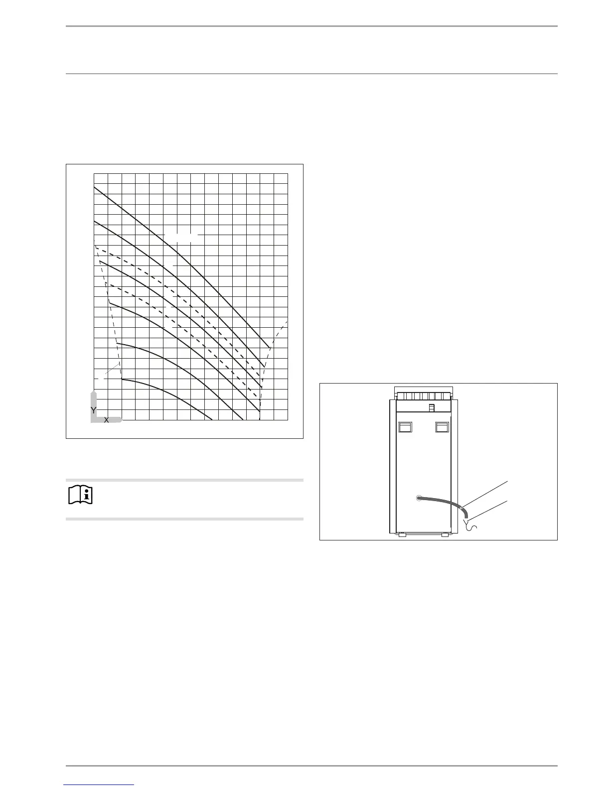
Check the brine concentration:
Determine the density of the ethylene glycol/water mixture,
e.g. with a hydrometer.
Using the actual density and temperature, you can check the actual
concentration in the diagram.
1,10
1,09
1,08
1,07
1,06
1,04
1,03
1,02
1,01
1,00
0,99
0,98
-20 0 20 40 60 80 100
50 Vol.-%
0
1,05
40
33
30
25
20
10
A
26�03�01�1914
X Temperature [°C]
Y Density [g/cm³]
A Frost protection [°C]
Note
The quoted details refer to ethylene glycol (see "Speci-
fication").
Thermally insulate all brine pipes with diffusion-proof material.
The integral pressure expansion vessel is opened and sealed at
the factory. The pre-charge pressure of the expansion vessel on
the brine side should be checked and adjusted, if required. For
this, the system fill pressure must be higher than the pre-charge
pressure plus max. brine pump pressure differential.
For geothermal probes, the expansion vessel is suitable for a fill
volume of up to 600l.
11.5 Heating water connection
The heating system to which the heat pump is connected must be
installed by a qualified contractor in accordance with the water
installation diagrams that are part of the technical guides.
Thoroughly flush the pipework before connecting the heat
pump. Foreign bodies, such as rust, sand and sealant, can
impair the operational reliability of the heat pump. We rec-
ommend installing our filter assembly in the heating return
(see chapter "Accessories").
To facilitate an easy connection to the heating system, the appli-
ance is supplied with plug-in connectors (see chapter "Fitting the
push-fit connector").
Connect the heating system to the "heating flow" and "heat-
ing return" connections. Check for tightness.
Ensure the correct connection of the heating flow and return.
When sizing the heating circuit, observe the maximum avail-
able external pressure differential (see chapter "Specification
/ Data table").
Provide thermal insulation in accordance with applicable
regulations.
At the factory, the pressure expansion vessel on the heating side
is sealed in the open position at the cap valve.
Safety valve
26�03�01�1855
1
2
1 Drain
2 Discharge outlet
Size the discharge outlet so that water can drain off unim-
peded when the safety valve is fully opened.
Ensure that the safety valve drain is open to the outside.
Install the safety valve drain with a constant fall to the dis-
charge outlet. When installing the drain, never kink the pipe.

 Loading...