www.stiebel-eltron.com WPF | WPF cool | 33
INSTALLATION
Power supply
12.3 Sensor installation
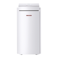
Outside temperature sensor AFS 2 (included in the pack
supplied)
The temperature sensors have a significant influence on the func-
tion of your heating system. Therefore ensure the correct seating
and adequate insulation of sensors.
26�03�21�0052
Install the outside temperature sensor on a north or north-eastern
wall. Minimum clearances: 2.5 m above the ground, and 1 m to
the side of windows and doors. The outside temperature sensor
should be freely exposed to the elements but not placed in direct
sunlight. Never mount the outside temperature sensor above win-
dows, doors or flues.
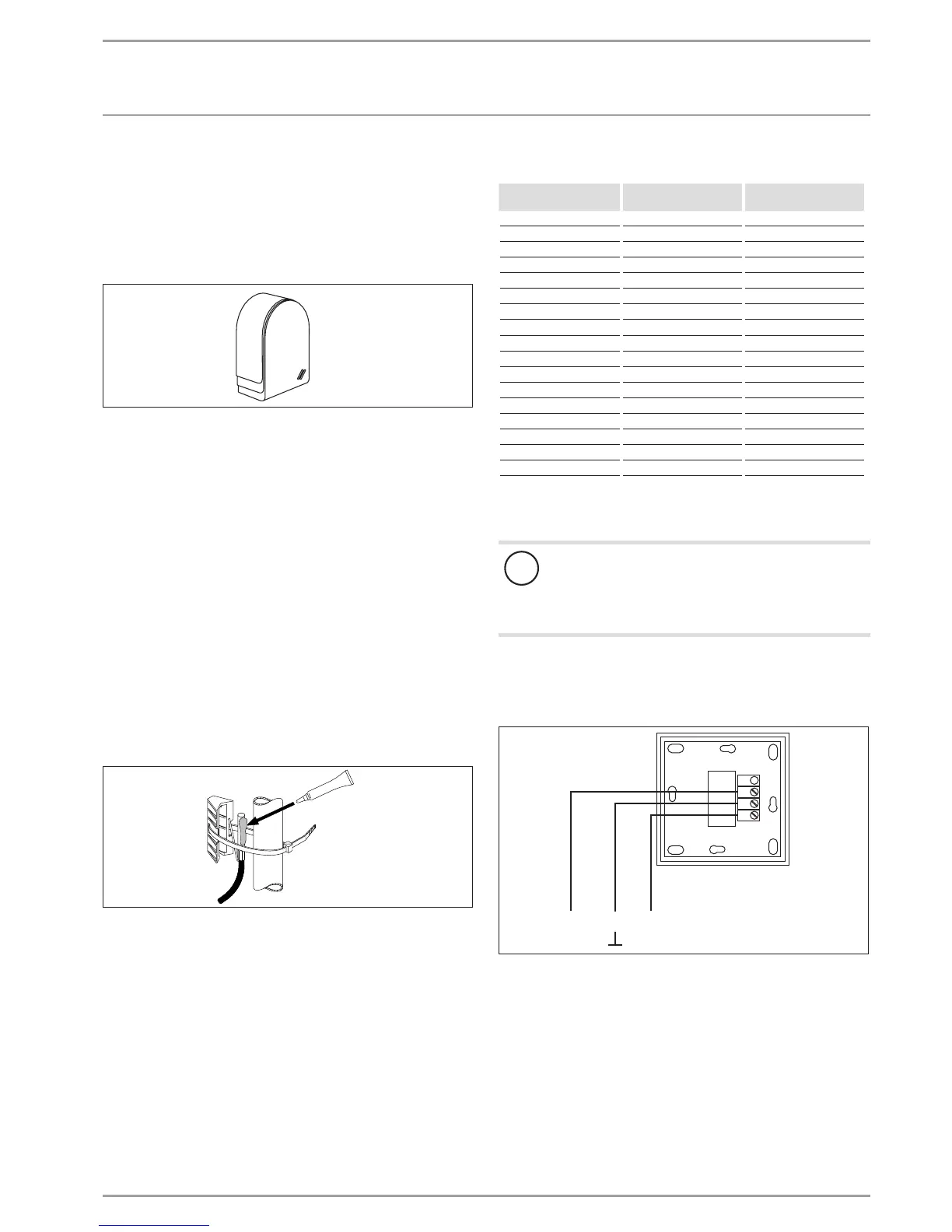
Connect the outside temperature sensor to terminal X2(T(A)) and
to the earth block for low voltage X26 of the appliance.
Installation:
Remove the cover.
Secure the lower part with the screw supplied.
Connect the cable.
Replace the cover. The cover must audibly click into place.
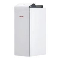
Contact sensor AVF 6
This sensor is required when using a mixer circuit.
Installation information:
26�03�01�1431
Clean the pipe.
Apply heat conducting paste.
Secure the sensor with a cable tie.
Sensor resistance values
Temperature in °C PT 1000 sensor
Resistance in Ω
KTY sensor
Resistance in Ω
- 30 843 1250
- 20 922 1367
-10 961 1495
0 1000 1630
10 1039 1772
20 1078 1922
25 1097 2000
30 1117 2080
40 1155 2245
50 1194 2417
60 1232 2597
70 1271 2785
80 1309 2980
90 1347 3182
100 1385 3392
110 1423 ---
120 1461 ---
12.4 Safety temperature controller for underfloor
heating system STB-FB
!
Material losses
In case of failure, in order to prevent an excessively high
flow temperature in the underfloor heating system, we
generally recommend the use of a safety temperature
controller to limit the system temperature.
12.5 Remote control FE 7
Connection array FE 7
3
1
1 2 3
26�21�01�0008
The FE 7 remote control enables you to adjust the set room tem-
perature for heating circuit 1 or heating circuit 2 by ± 5 °C in
automatic mode only. You can also change the operating mode.
Connect the remote control to terminals Fernb.1 (Rem.con.1) and
Fernb.3 (Rem.con.3) at terminal block X2 and earth block for low
voltage X26 of the appliance.

 Loading...