32 |WPF | WPF cool www.stiebel-eltron.com
INSTALLATION
Power supply
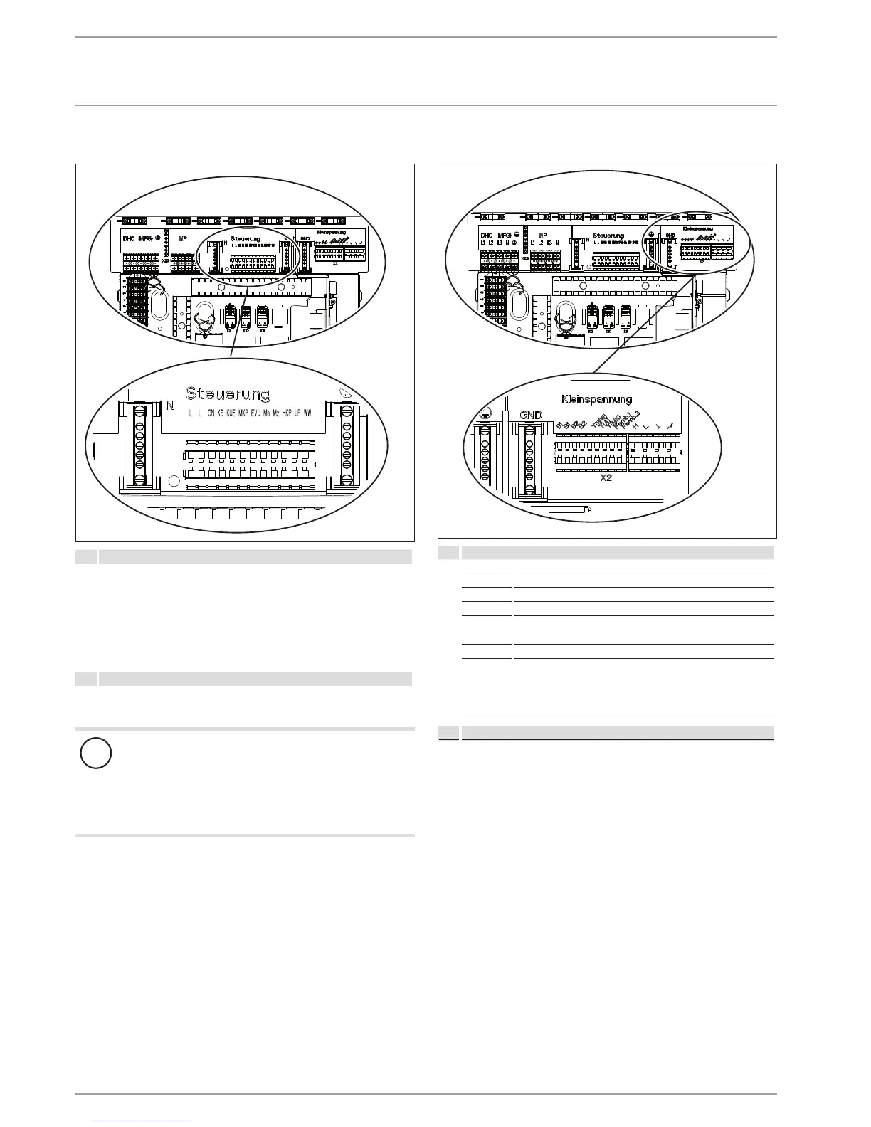
12.2.3 Control voltage
D0000036217
X4 Control voltage (control outputs)
ON
KS
KUE
MKP
M(A)
M(Z)
HKP
UP
DHW
Compressor signal
Brine pump signal
Cooling
Mixer circuit pump and N (X25), PE
Mixer open
Mixer closed
Heating circuit pump and N, PE
Pump
DHW
X4 Control voltage (control inputs)
L, N, PE Power supply
EVU Enable signal
!
Material losses
Only connect energy efficient circulation pumps to
the pump connections if they have been approved
by us.
If energy efficient circulation pumps are used that have
not been approved by us, use a relay with a breaking ca-
pacity of at least 10A/250VAC or our WPM-RBS relay set.
Route cables and leads through the strain reliefs.
Check the function of the strain relief fittings.
If no voltage is applied to the power supply utility enable signal,
the heat pump will not start. The message “power-OFF” appears
on the controller. In this event, install a jumper across “EVU” and
phase “L”.
12.2.4 Low voltage, bus cable
D0000036218
X2 Low voltage
B1 Heat pump flow temperature sensor
B2 Heat pump return temperature sensor
T (WW) DHW cylinder sensor and earth (X26)
T(A) Outside temperature sensor and earth (X26)
T(MK) Mixer circuit temperature sensor and earth (X26)
Fernb. 3 Connection for FE 7
Fernb. 1 Connection for FE 7 and uponor DEM WP module
+ CAN bus for remote control
⊥
L
H
GND Ground for temperature sensor
Route cables and leads through the strain reliefs.
Check the function of the strain relief fittings.

 Loading...