30 |WPF | WPF cool www.stiebel-eltron.com
INSTALLATION
Power supply
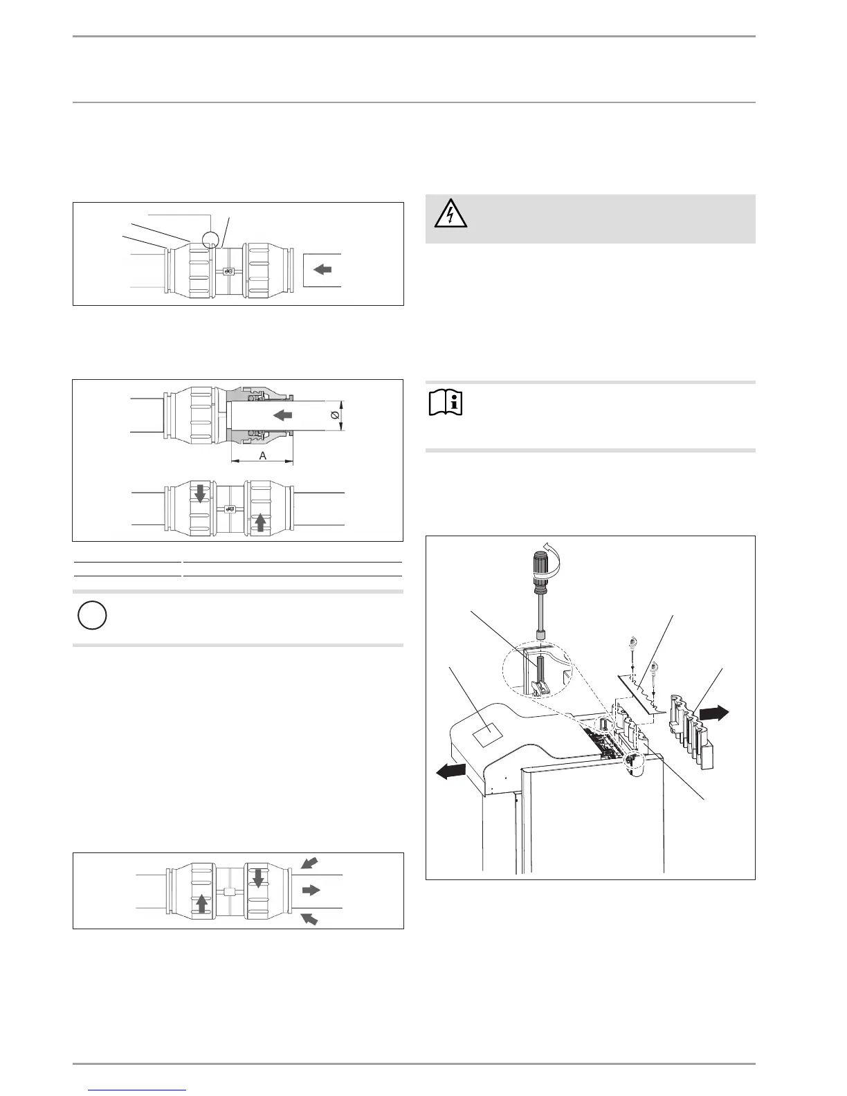
Making the push-fit connection
The connector must be in its relaxed position before the pipe is
inserted. In this position, there is a small gap between the screw
cap and main body.
26�03�01�0693
3
1
2
4
1 Retainer
2 Screw cap
3 Gap between screw cap and main body
4 Main body
26�03�01�0693
Pipe Ø 28 mm
Depth of insertion A 44 mm
!
Material losses
Pipe ends must be deburred.
Always use a pipe cutter to trim pipes.
Push the pipe through the O-ring into the push-fit connector
until it reaches the prescribed insertion depth.
Tighten the screw cap by hand against main body as far as it
will go. This locks the push-fit connection.
Undoing the push-fit connection
If the push-fit connectors later need to be undone, proceed as
follows:
Turn the screw cap anti-clockwise until there is a narrow gap
of approx. 2mm. Press the retainer back with your fingers
and hold on to it.
Pull out the inserted pipe.
26�03�01�0693
12. Power supply
12.1 General
WARNING Electrocution
Before any work, isolate the appliance from the
power supply at the control panel.
Connection must only be carried out by a qualified contractor and
in accordance with these instructions.
Permission to connect the appliance may need to be obtained from
your local power supply utility.
Observe chapter "Preparations / Electrical installation".
12.2 Power supply
Note
Before making the electrical connections you need to fill
the heating system (see chapter "Heating water connec-
tion").
Terminals are located at the appliance control panel under the
top cover.
Use appropriate cables in accordance with local regulations for
all connections.
5
1
4
2
3
D0000036136
1 Cover strip
2 Hexagon bolt (SW 7)
3 Cover
4 Front thermal insulation piece
5 Rear thermal insulation piece
Remove the cover strip.
Undo the hex bolts with a socket spanner and remove the
cover towards the front.
Remove the rear thermal insulation piece.
Route the cables through the cable entry in the front thermal
insulation piece.

 Loading...