WWW.STIEBEL-ELTRON.COM WPF 20/27/40/52/66 | 17
INSTALLATION
TROUBLESHOOTING
13. Troubleshooting
Checking the IWS settings
3
2
1
4
26�03�01�0661
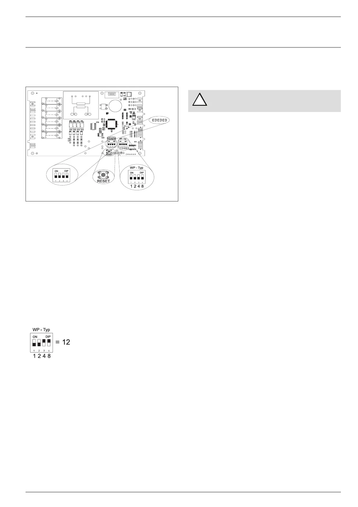
1 LEDs
2 DIP switch (BA)
3 Reset button
4 DIP switch (heat pump)
The control panel with the "Internal heat pump controller" (IWS II)
becomes accessible after removing the front hood. The following
list the adjustments of the IWS II required for the WPF:
13.1 DIP switch (heat pump)
The DIP switch (heat pump) enables the pre-selection of the
various compressor systems. Subject to the system heat pump
type. for the WPF this was set to 12 at the factory.
If the WPF is to be operated as a module with another WPF. this
setting (heat pump) remains at 12.
f Please check whether the DIP switch (heat pump) is set
correctly.
The correct position of the slide switch can also be checked on
control level 3 on the WPM II. The display should indicate a C under
parameter "Type IWS".
13.2 DIP switch (BA)
Switches 1, 2 and 3 have no relevance to the WPF.
Position switch 4
Switch ON : STAND-ALONE operation
STAND-ALONE operation is only possible if a heat pump type has
been allocated to the WPM II under parameter IWS TYPE.
Should the WPM II heat pump manager develop a fault. the heat
pump can be operated in STAND-ALONE mode in an emergency.
In this operating mode. there is no communication with the WPM
II. The heat pump regulates to a fixed temperature: it starts up at
50 °C and shuts down at 55 °C. For this. 230 V must be applied to
terminal X4/2. and a contact sensor AVF 6 connected as a return
temperature sensor at sensor terminals X2/4 and X2/5. The
sensor must be connected to the heating return (chapter Device
description). The operating mode is indicated by the green LED
on the right.
Risk of damage!
For STAND-ALONE operation. remove the jumper
between X4/1 and X4/2.
13.3 LEDs
Red LED:
The LED flashes when a heat pump fault occurs once. The system
will be shut down.
The red LED illuminates steady if more than 5 heat pump faults
occur within 2 hours. The system will be shut down permanently.
If the red LED is flashing or illuminated steadily, voltage of 230V
is present at the fault output (terminal X4/3).
To delete the faults from the IWS II. select Reset WP and reset
by pressing PRG on the IWS II. The internal counter will then be
returned to zero.
Heat pump faults displayed by the LED: High pressure fault / low
pressure fault. central fault message and hardware faults at the
IWS II (see fault list).
Green centre LED: Flashes during the initialisation and becomes
steady after the BUS address has been allocated. Communication
to the WPM II is only then established. This is only relevant for the
WPF. if the control unit is replaced. otherwise the unit is initialised
at the factory.
Green r.h. LED: Illuminates steady if STAND-ALONE operation has
been selected.
Reset button
In case of incorrect initialisation. see chapter 5.4.1 in the operating
and installation instructions of the WPM II.

 Loading...


