Page 8 Technical Information 11.2013
TI_11_2013_30_01_01.fm
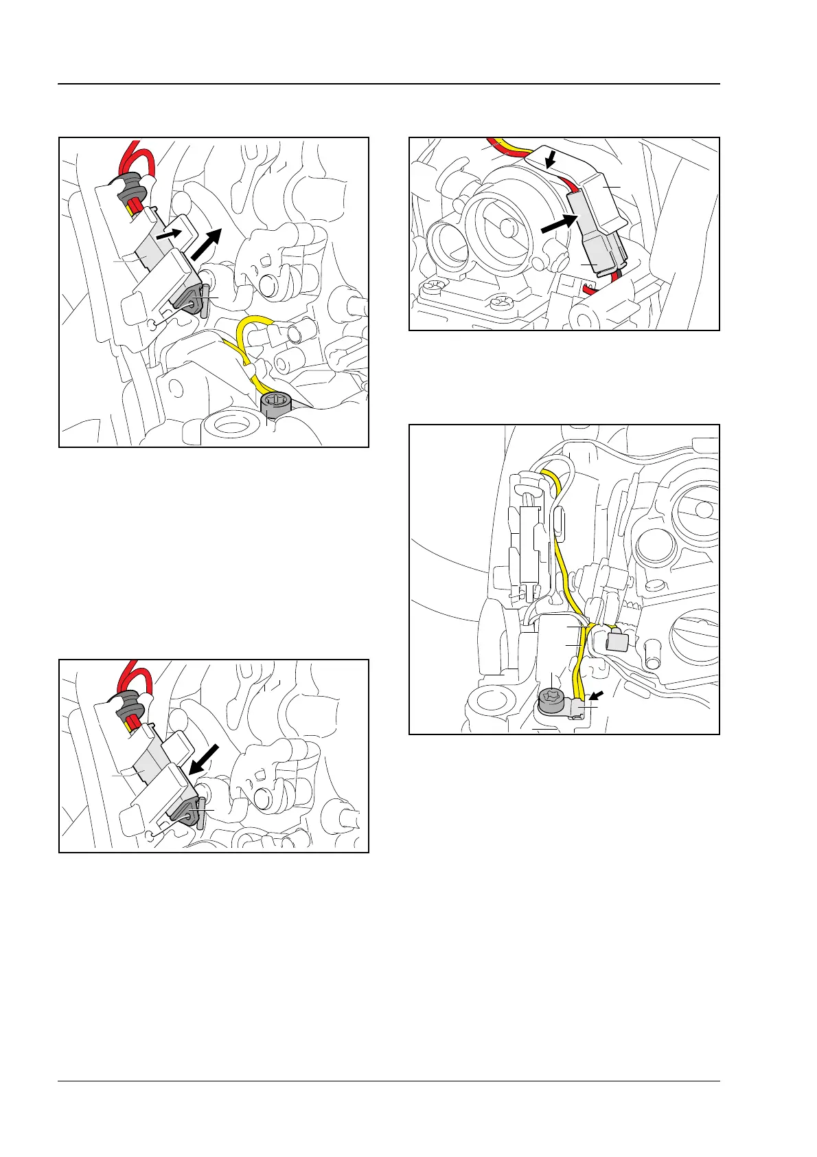
. Take out the screw (5).
. Remove protective cap (6) from diagnostic
socket.
. Push the locking tab (arrow) in direction of
carburetor and pry the diagnostic socket (7) and
grommet out of the guide.
. Remove the wiring harness.
6.3.2 Installing the Wiring Harness
. Push the diagnostic socket (7) and grommet
into the guide in the crankcase – red wires must
be on top.
. Fit the protective cap (6) on the diagnostic
socket.
. Join the connector (3) and fit it in the connector
housing (4).
. Push the red wire (9) over the yellow wire (8)
into the guide (arrow).
. Fit ground wire flag terminal (10) in the
guide (arrow).
. Fit and tighten the screw (5) to 35 lbf in (4 Nm).
. Position the yellow ground wire to the diagnostic
socket (11) over the other yellow ground wire to
the contact spring (12) and push into the guides.

 Loading...