StoneL publication 105431revC
7 PI 70 en Prism PI | 11
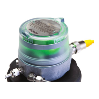
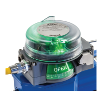
4.1 Sensor/switching modules
4.1.2 NAMUR sensor (45S)
Reference controlled installation drawing #105432 for
proper intrinsic safe installation details. Find document
in the Appendix on page30 or at www.StoneL.com/
en/products/prism/installation-manuals
STOP
Expanded dead band setting feature
The Prism PI sensing module has the capability of changing the dead
band of the open sensor from the factory setting of 30% of stroke
to an expanded setting of 45%. It may be necessary to perform this
procedure for applications in which the valve stroke varies between
normal batch processing and SIP/CIP evolutions.
1. Ensure the open and closed sensors have been set before running
this procedure. Valve can be in either the open or closed position.
2. With power applied to the Sensing Module press and hold both
SET OPEN and SET CLOSED buttons until the red and green LEDs
ash (ve seconds). Release buttons.
3. Press and hold SET OPEN button until the green LED is lit (one
second). Release button. Open sensor now has a 45% dead band.
4. To revert back to the factory default of 30% dead band, press and
hold both SET OPEN and SET CLOSED buttons until the red and
green LEDs ash (ve seconds). Release buttons.
5. Press and hold SET CLOSED button until red LED is lit (one second).
Release button.
6. Settings are retained even after power is removed.
Caution: Performing this procedure will cause the sensor
inputs to change states. Performing this procedure is not
recommended during a live process.
Wiring diagrams
Set Open
Set Closed
push button
LED indication bar
PWR
-
+
SOL OPEN CLOSEDSOL
+
+
- -+
-
Valve
Open LED
Solenoid
power LED
Y
R
Valve
Closed LED
G
Signal
OPEN +
MALE (PINS)
MALE (PINS)
1
1
2
2
5
6
4
5
3
4
3
6-PIN MICRO CONNECTOR (M12)
6-PIN MINI CONNECTOR
OPEN -
SOL PWR +
CLOSED +
CLOSED -
Pin
1
2
3
4
5
SOL PWR -6
6
Common receptacle options pin-out
Signal
OPEN +
4-PIN MICRO CONNECTOR (M12)
CLOSED +
CLOSED -
OPEN -
Pin
1
2
3
4
MALE (PINS)
1 2
4
3
Specications
Conguration (2) NAMUR sensors (EN 60947-5-6; IS)
Voltage range 5 - 25 VDC
Current ratings Target present
Target absent
current < 1.0 mA
current > 2.1 mA
Use with intrinsically safe repeater barrier. NAMUR sensors conform to EN 60947-5-6 standard.
Bench test procedure and sensor setting instructions
Power must be applied to both sensors to ensure proper circuit
operation. Use a 24VDC power supply. A series load resistor is not
required when bench testing.
1. Connect 24VDC+ to the CLOSED + and OPEN + terminals.
Connect 24VDC- to the CLOSED - and OPEN - terminals.
2. Operate actuator to the closed position.
3. Press and hold SET CLOSED button until Closed LED is lit (2
seconds). Release button.
4. Operate actuator to the open position.
5. Press and hold SET OPEN button until Open LED is lit (2 seconds).
Release button. Both Open and Closed LEDs will be lit during mid-
travel.
6. Setpoints are retained even after power is removed.
Note
If using only one of the sensors for valve position feedback, the Closed
sensor must be used.
 Loading...