7 PI 70 en16 | Prism PI
StoneL publication 105431revC
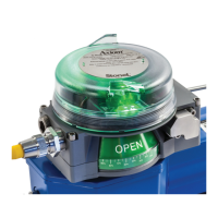
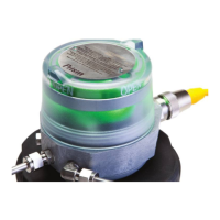
4.2 Valve communication terminals (VCT)
4.2.1 VCT with DeviceNet™ communication (92S & 92W)
Expanded dead band setting feature
The Prism PI sensing module has the capability of changing the dead
band of the open sensor from the factory setting of 30% of stroke
to an expanded setting of 45%. It may be necessary to perform this
procedure for applications in which the valve stroke varies between
normal batch processing and SIP/CIP evolutions.
1. Ensure the open and closed sensors have been set before running
this procedure. Valve can be in either the open or closed position.
2. With power applied to the Sensing Module press and hold both
SET OPEN and SET CLOSED buttons until the red and green LEDs
ash (ve seconds). Release buttons.
3. Press and hold SET OPEN button until the green LED is lit (one
second). Release button. Open sensor now has a 45% dead band.
4. To revert back to the factory default of 30% dead band, press and
hold both SET OPEN and SET CLOSED buttons until the red and
green LEDs ash (ve seconds). Release buttons.
5. Press and hold SET CLOSED button until red LED is lit (one second).
Release button.
6. Settings are retained even after power is removed.
Caution: Performing this procedure will cause the sensor
inputs to change states. Performing this procedure is not
recommended during a live process.
Attention: Any external auxiliary device connected to the
VCT module shall be ground isolated.
Wiring diagrams
V+ V-
CAN
H
CAN
L
Ain
+
Ain
-
OUT1
-
OUT2
-
24
VDC
SH
Set Open
Set Closed
Valve Open/
Closed LEDs
Solenoid
power LEDs
Module/network
status LED
R/G
Y Y
R G
Valve Open/
Closed LEDs
G R
Specications
Communication protocol DeviceNet™
Conguration (2) Discrete inputs (sensors)
(1) Auxiliary analog input (4-20 mA)
(2) Discrete outputs (solenoids)
Input voltage 11 - 25 VDC via DeviceNet™ network
Output voltage 24 VDC
Analog input impedance 254 ohms
Quiescent current No analog input, no outputs energized:
45mA @ 24VDC; 69 mA @ 11VDC
Current consumption
(coil energized)
66 mA @ 24 VDC - 0.5 w coil (1N)
83 mA @ 24 VDC - 0.9 w coil (1K)
Maximum output current 167mA (all outputs combined)
Default address 63 (software assigned)
Default baud rate 125K (software selectable 125K, 250K or 500K baud)
Messaging Polling, cyclic and change of state
DeviceNet™ type 100
Bit mapping
Inputs (3 bytes)
Byte 0, bit 0 = red LED / valve closed
Byte 0, bit 1 = green LED / valve open
Byte 0, bit 7 = fault bit
Byte 1, bits 8-15 = 4-20 mA analog input
Byte 2, bits 16-23 = 4-20 mA analog input
(4-20 mA analog input 0-10,000 scaling)
Outputs (1 byte)
Byte 0, bit 0 = solenoid 1
Byte 0, bit 1 = solenoid 2
Byte 0, bit 2 = wink
Byte 0, bit 3 = remote set closed
Byte 0, bit 4 = remote set open
Byte 0, bit 7 = wireless link enabled
Bench test procedure and sensor setting instructions
To test sensors, use a 24VDC power supply. No series load resistor is
required.
1. Apply power across the V+ and V- terminal points.
2. Operate actuator to the closed position.
3. Press and hold SET CLOSED button until red LED is lit (2 seconds).
Release button.
4. Operate actuator to the open position.
5. Press and hold SET OPEN button until green LED is lit (2 seconds).
Release button.
6. Setpoints are retained even after power is removed.
A functioning DeviceNet™ network is required to test
communications and solenoids.
WARNING
Do not apply external power to the output terminals. This will
cause permanent damage to the unit.
Module/Network Status LED status
DeviceNet™ status LED Fault description
LED o Device not powered, or is alone on the bus
Solid green Device is online and allocated to a master
Flashing green Device is online, but not allocated to a master
Flashing red (Minor Fault) Communication to protocol controller has failed
Flashing red (Minor Fault) Connection to DeviceNet™ master has timed-out
Flashing red (Minor Fault) Address/baud switches are not equal to currently online
values
Solid red (Major Fault) Device has detected another device on the bus with the
same DeviceNet™ address
Solid red (Major Fault) Device has detected a CAN network Bus-o fault
Common receptacle options pin-out
Signal
Shield
MALE (PINS)
MALE (PINS)
1
1
2
2
5
5
4
4
3
3
5-PIN MICRO CONNECTOR (M12)
5-PIN MINI CONNECTOR
V +
V -
CAN H
CAN L
Pin
1
2
3
4
5
 Loading...