7 PI 70 en4 | Prism PI
StoneL publication 105431revC
Specications
Materials of construction
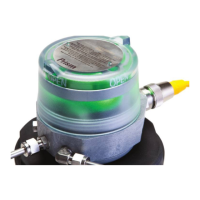
Cover Clear polycarbonate
Housing & mounting system Fiber reinforced polycarbonate and stainless steel
Fasteners Stainless steel
Mounting system Fiber reinforced polycarbonate and stainless steel
Seals Buna N
Valve manifold Polycarbonate with stainless steel reinforced
⁄“NPT porting
Trigger (magnetic) Polysulfone with black chromated zinc
reinforcement
Operating life Over 1 million cycles
Operating temperature range
Unit without solenoid
Unit with solenoid
-20° C to 60° C (-4° F to 140 ° F)
See 1.8 Pneumatic valve specifications
Enclosure protection Type 4, 4X, 6 and IP66 / IP67
Warranty
Sensing & communication
module
Five years
Mechanical components Two years
Unit weights
Standard stroke 0.77 kg / 1.7 lb
Long stroke 0.95 kg / 2.1 lb
Unit dimensions
Standard stroke no visual indicator Unit height
Cover removal clearance
84.1 mm [3.31 in]
25 mm [1 in]
Standard stroke with visual indicator Unit height
Cover removal clearance
107.9 mm [4.01 in]
25 mm [1 in]
Long stroke Unit height
Cover removal clearance
163.3 mm [6.43 in]
70 mm [2.75 in]
Position sensing
Accuracy 1.0 mm [0.04 in]
Repeatability 0.5 mm [0.02 in]
Setting buffer (factory settings) Open - 25% of stroke length
Closed - 25% of stroke length up to 3.2 mm [0.125 in]
Deadband (factory settings) Open - 30% of stroke length
(variable; based on actual stroke)
Closed - 30% of stroke length or 3.8 mm [0.15 in]
(whichever is less)
Environmental conditions
Location Indoor and outdoor
Maximum altitude 5000 m
Maximum humidity 90%
Pollution degree 4
Ratings and approvals*
See page28 or StoneL.com/approvals
* Only models listed on StoneL’s official website are approved per specific rating.
1.7 Specications for all models
See page10 for function specic details.
6
8
5
9
4
10
11
7
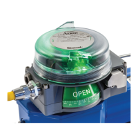
1.6 Assembly drawing
1. Title plate
2. Cover
3. Trigger
4. Sensing module
5. Internal ground lug
6. Body screws
7. Body
8. Mounting screws
9. Trigger assembly shaft
10. Mounting plate
11. Actuator
1
2
3
 Loading...