StoneL publication 105431revC
7 PI 70 en Prism PI | 7
2 Assembly and mounting
2.1 Instructions
Steps
Refer to Prism PI assembly gure on page8 when performing
mounting and assembly procedures. Prism PI unit and mounting kit
are supplied separately. From Prism PI shipping container, ensure
items A, and F are present. From the mounting kit, ensure items G, H, I,
and J are present.
1. From the mounting kit package, locate the trigger shaft (ItemG),
Prism mounting plate (ItemJ), and mounting plate fasteners
(ItemH). Ensure unit O-ring (Item I) and mounting plate O-ring
(ItemK) are present in the mounting plate.
2. Thread the trigger shaft into the actuator (ItemL) (it is
recommended that a drop of blue Loctite® be used on the trigger
shaft threads). Tighten to approximately 15 - 20 in.lbs (1.7 - 2.3Nm)
with a small adjustable wrench.
3. Place the mounting plate onto the actuator and fasten down with
provided screws (2-4). (use of blue Loctite® on these screws is
optional). Tighten to approximately 15 - 20 in.lbs (1.7 - 2.3Nm).
4. Take o cover (ItemB) and remove the trigger assembly (ItemF)
from within the unit.
5. Place Prism PI unit (ItemA) onto the mounting plate in the
orientation desired (Prism PI body can be rotated on the mounting
plate in 45° increments). Tighten the two body screws (ItemD)
with a M3 allen wrench to approximately 25 - 30 in.lbs (2.8 -
3.4Nm).
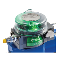
6. Back out the trigger assembly adjustment screw (ItemE)
approximately ⁄” with a M2 allen and place the trigger assembly
into the corresponding slot of the sensing module (ItemC), with
a nger, press down rmly onto the trigger assembly shaft (See
Detail-Fig.1).
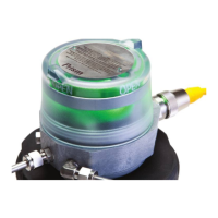
7. Turn the trigger assembly adjustment screw until the yellow marks
on the trigger assembly are ush with the yellow marks on the
sensing module (See Detail-Fig.2) To remove trigger assembly
from shaft, turn in adjustment screw until released.
8. After all wiring and sensor setting procedures have been
completed, re-install cover and place unit in service.
Special notes:
• Mounting of the Prism PI requires a StoneL mounting kit specic to
the actuator the Prism PI is to be mounted to.
• In high cycle or high vibration applications, blue Loctite® may
be used on the Trigger shaft threads (ItemG) and the Prism PI
mounting plate screws (ItemH).
• It is highly recommended that exhaust port E be tted with a low
restriction muer or breather vent cap to prevent ingestion of
water or debris into the pneumatic valve.
Fig. 2 Sensing module detailFig. 1 Trigger assembly detail
Trigger assembly
adjustment screw
Yellow alignment
marks
 Loading...