StoneL publication 105431revC
7 PI 70 en Prism PI | 15
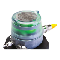
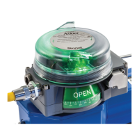
4.1.4 Expeditor, long stroke (81S & 81W) continued
Description of operation
The Prism Expeditor is a valve monitoring and control package for
linear actuators that provides open/closed, intermediate positioning,
and valve position feedback functionality. Basic operation and
intermediate control is accomplished by 24VDC and a 4-20mA
output signal from a control system.
Basic operation
The Prism Expeditor module is powered through the VDCIN terminals
and 24VDC must be present in order to calibrate the unit. The
CNTRLIN signal is also required for basic operation of the unit.
To stroke the valve fully closed position, apply a 4mA signal. To stroke
the valve fully open, apply a 20mA signal.
Intermediate position control
Intermediate positioning is accomplished by varying the 4-20mA
signal between 7.2mA and 16.8mA.
Position feedback
The Prism Expeditor long stroke provides two dierent valve position
feedback signals, a 4-20mA signal and two discrete sensor signals for
valve open and valve closed.
Connect a 4-20mA input signal to the POS FB terminals to monitor
valve position. Connect to the CLOSED and OPEN terminals to
monitor valve position from the two discrete sensors.
Note
Applying an out of range 4-20mA signal (<3.4mA or >21.1mA)
will drive valve to the 0% position and unlock the Wireless Link
control override functionality. Wireless functionality allows remote
monitoring, position control and TEACH capabilities. See page22
for Wireless Link user guide.
WARNING
Do not apply external power to the primary or secondary
solenoid terminals. This will cause permanent damage to the unit.
Calibration
The VDCIN terminals must be connected to a 24VDC power source
and unit connected to supply air.
1. Actuate the valve to the 0% position, red LED will be lit.
2. Press and hold the TEACH button for 2 seconds. The valve will
cycle open and closed one or more times while determining the
valve operating characteristics. The red, green, and yellow LEDs will
ash intermittently during these cycles.
3. Calibration will nish with the valve at the commanded position
and the appropriate LED will be lit.
Caution: Read all instructions prior to performing this
procedure.
WARNING
Valve/actuator will automatically stroke while performing this
procedure. Ensure hands are clear from the trigger assembly.
Specications for Wireless Link
Communication Bluetooth® technology; single mode
(not compatible with Bluetooth® Classic)
Frequency band 2.402-2.480 Ghz
Transmit power 4dBm or ~2.5 milliwatts
Data rate 1 Mbit/second; eective information transmit rate
~10 Kbits/second
Range Up to 100 meters (330 feet) in free space. Range is
reduced by obstructions between handheld device and
Wireless Link VCT. Line of site is not necessary.
Registrations FCC, IC, CE
CE compliance Exceeds industrial compliance standards
VCT identication VCTs in range will be displayed in order of signal
strength
VCT link One device accessed at a time between client (hand-
held device) and server (VCT). Each server accessed by
one client at a time
Application StoneL Wireless Link available from the App store
Hand-helds Compatible with iPhone® and iPad® with iOS 8 or later
 Loading...