3 Description
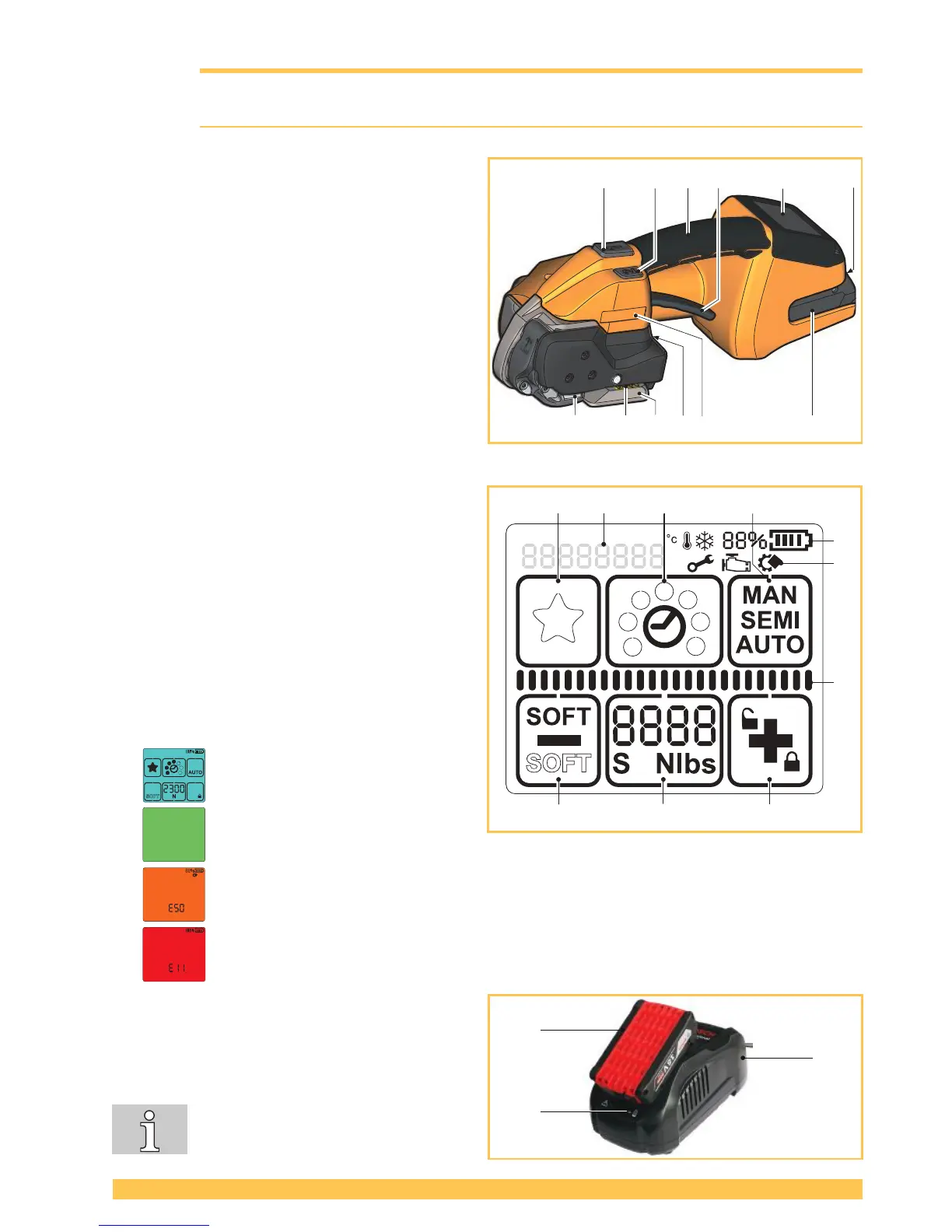
3.1 Design
1 Tensioning button
2 Welding button
3 Handle
4 Rocker lever
5 Operating panel
6 Unlock button, battery
7 Battery
8 Type designation
9 Strap guide indicator
10 Serial number (XJJMMYYYY)
X A=STB 71, B=STB 73, C=STB75
JJ Year
MM Month
YYYY consecutive number
11 Welding device
12 Tensioning device
Operating panel
1 Keypad "Favourite"
2 Keypad "Welding time"
3 Keypad "Operating mode"
4 Keypad "Plus & Keylock"
5 Keypad "Tensioning force"
6 Keypad "Minus & Soft tension"
a Display "Battery charge status"
b Display "Information symbols"
c Status indicator bar “Tensioning/Welding“
d Display "Messages"
Background lighting
● Display activated.
● Welding process is nished, tool
can be removed (Section 5.1).
● Application error: temporary system error, can be rectied by the operator (Section 6.8).
● Tool fault: static system error, rectify error (Section 6.8). If the error cannot be rectied
Service department.
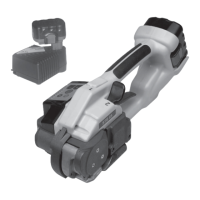
Battery and charger
1 Charger
2 Battery
3 LED indicator
For detailed information, refer to the
operating instructions for the battery
and the charger.
a
b
c