Do you have a question about the StressTel T-MIKE E and is the answer not in the manual?
Key elements for proper ultrasonic test equipment use.
Requirement for adequate training in ultrasonic testing procedures.
Procedure to compensate for fixed delay of ultrasonic transducer.
How temperature variations affect sound velocity and zero calibration.
Criteria for selecting a good condition transducer for testing.
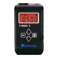
How the T-Mike E measures thickness using ultrasonic waves and velocity.
Compensating for transducer and electronics time delay via a PROBE recognition operation.
Calibrating the T-Mike E's velocity using a material sample or known velocity.
Overview of the Initial Setup procedure for seldom-changed settings.
Procedure for selecting the backlight status (ON or OFF).
How to turn the T-Mike E on and its initial display.
Performing the probe zero function to compensate for transducer delay.
Setting up and calibrating the T-Mike Programmable unit.
Method to transfer settings from a T-Mike E to a T-Mike Programmable.
Procedure to program the T-Mike Programmable using PC software.
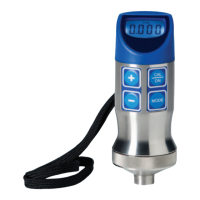
Setting up and calibrating the T-Mike Basic unit.
Procedure for selecting a material for measurement on the T-Mike Basic.
Changing settings like units of measure and backlight on the T-Mike Basic.
Tips on using the backlit LCD display to conserve battery life.
Guidance on cleaning surfaces and applying couplant for accurate readings.
Importance of material properties and consistency for measurement accuracy.
Checks for common issues with the transducer and connecting cable.
Information regarding the "memory" effect and proper use of NiCad batteries.
Troubleshooting issues related to the keypad's function and replaceability.
Precautions for the fragile LCD display and its replacement.
Details of the manufacturer's warranty for instruments and transducers.
Method for calibrating thickness using two calibration blocks.
Procedure to switch between one-point and two-point calibration modes.
| Application | Thickness measurement |
|---|---|
| Technology | Ultrasonic |
| Measurement Range | 0.63 mm - 500 mm (depending on transducer) |
| Resolution | 0.01 mm or 0.001 inch |
| Power Supply | 2 AA Batteries |
| Weight | 300 g |
| Dimensions | 150 mm |