259.00.63
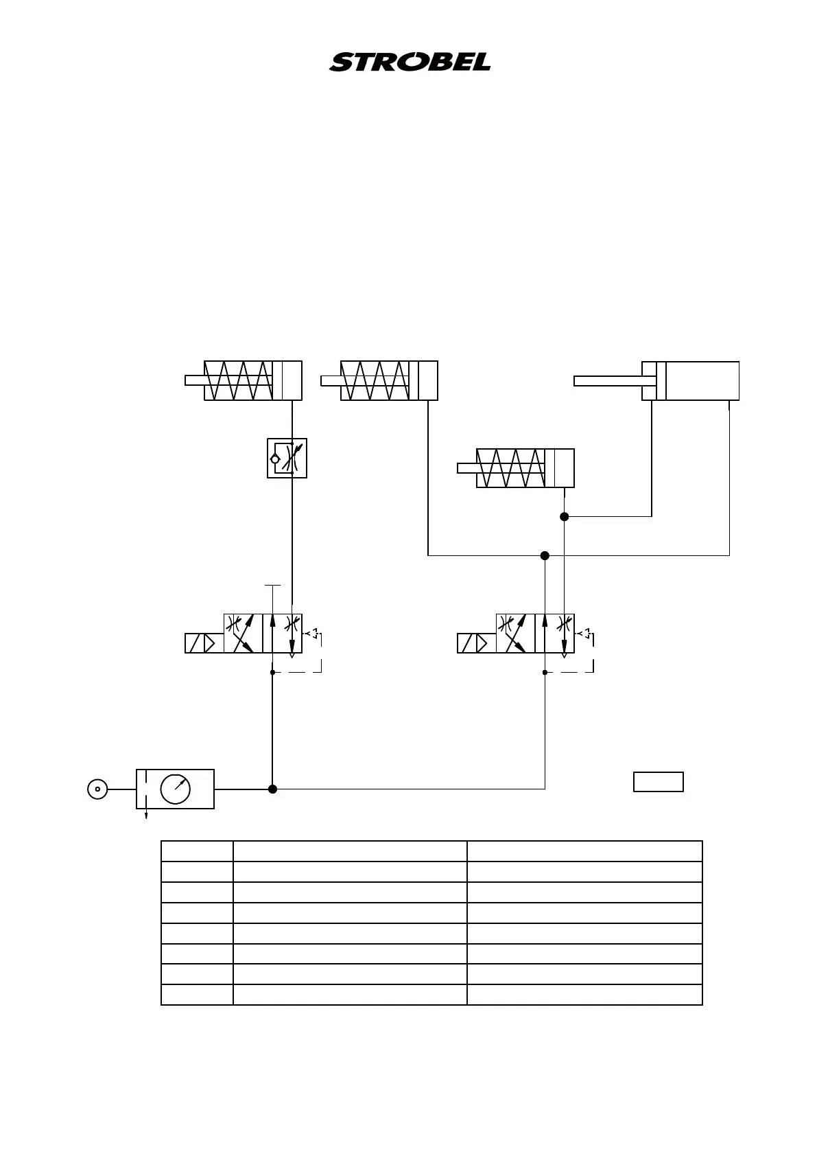
Pneumatischer Schaltplan Kl. 310D-R, 3100D-R
Pneumatic circuit diagram cl. 310D-R, 3100D-R
0 Z 1 Wartungseinheit Service unit
1 V 1 4/2-Magnetventil "Lüftung" 3/2-solenoid-way valve "lifting"
1 V 2 4/2-Magnetventil "Riegel" 3/2-solenoid-way valve "spot tack"
1 V 10 Drosselrückschlagventil "Lüftung" Throttle non-return valve "lifting"
1 A 1 Zylinder "Lüftung" Cylinder "lifting"
1 A 2 Zylinder "Fadenspannung Riegel" Cylinder "thread tension spot tack"
1 A 3 Zylinder "Seitentransport" Cylinder "lateral feed"
1 A 4 Zylinder "Riegel" Cylinder "spot tack"
195.0551
0 Z 1
6bar
10bar max
1 V 10
1 A 1
1 A 2
1 A 3
1 A 4
1 V 1
B
P
R
A
1 V 2
B
P
R
A
 Loading...