2.0 YOUR RECEIVER
2.1 DEFAULT PIN: 1234
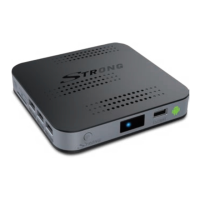
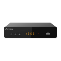
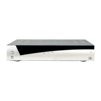
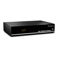
2.2 Front Panel
Fig. 1
1. Power switch To switch the receiver between ON/STANDBY modes.
2. Status indicator: Indicates status of reception and ON or OFF modes.
3. IR sensor: Receives Standby/On signal from the remote control.
4. USB: For connection of the USB adapter of the remote control.
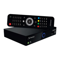
2.3 Rear Panel
Fig. 2
1. ANT IN To connect to your antenna for reception of broadcast signals.
2. ANT OUT To connect the terrestrial antenna signal to your TV set.
3. S/PDIF (optical) To connect your receiver to an digital audio amplifier.
4. LAN To connect to your router with a RJ 45 network cable.
5. HDMI To connect your receiver to your TV via HDMI cable.
6. Power To connect the included power adapter of 12 V.
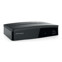
2.4 Side Panel
Fig. 3
1. SD card slot To insert an optional SD card.
2. USB: To connect USB devices like: mouse/keyboard/storage devices
2.5 Remote control
Fig. 4
1. q Turns the receiver ON/Standby
2. ! Turns the sound on or off.
3. ASPECT Switches between the screen settings “AUTO” and “Full”.
4. FAV Accesses the favourite channels lists.
5. TV/RADIO Switches between TV and radio mode
6. COLOUR BUTTONS Different functions in menu mode
7.
Opens the DTV menu/selection of wall papers
8. Returns to the Android menu/shows the latest used apps
9.
Returns to the previous menu or exits the App
10. pq Switches to the next/previous channel in viewing mode or moves
the highlight up/down in the menu.
11. tu Decreases/increases the volume level in viewing mode, navigates
through the menus or changes values of settings in a menu
12. OK Confirms a selection
13. VOL+/VOL- Increases/decreases the volume level
5
English