Service Information
18
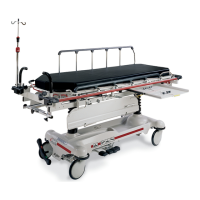
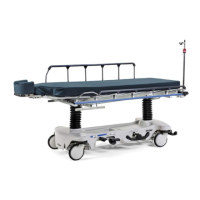
FOOT END HYDRAULIC JACK REMOVAL (BIG WHEEL BASE WITH 3−SIDED CONTROLS)
Required Tools:
1/2” Socket 3/8” Drive Ratchet Pliers
1. Remove the litter top from the stretcher (see page 14).
2. Lift the base hood off the base frame.
3. Remove the hair pin cotter and washer connecting the side control Big Wheel linkage toggle pivot plates
to the side control Big Wheel carriage weldment.
4. Remove the rue ring cotter and clevis pin connecting the side control Big Wheel rod end link to the yolk
weldment on the end control brake rod.
5. Remove the Big Wheel carriage assembly (see page 14).
6. Remove the two hex washer head screws and washers connecting the pump pedal link to the foot end
pump pedal assembly and pump connecting rod.
7. Remove the foot end pump pedal return spring.
8. Remove the cotter pin from the center of the foot end pump pedal assembly and slide out the pivot pin.
9. Slide the foot end pump pedal assembly up and over the foot end mounting bracket.
10. Remove the four hex washer head screws fastening the foot end mounting bracket to the base frame
and set the bracket aside.
11. Remove the foot end release rod from the release valve on the jack assembly by dislodging the release
pedal swivel from the pins on the release pedal weldment.
12. Dislodge the jack pump piston from the pump connecting rod.
13. Remove the two hex washer head screws holding the reservoir clamp.
14. Remove the jack assembly.
15. Reverse steps 1−11 to install the new jack.
NOTE
The jack descent rate is preset at the factory and adjustment is not recommended.
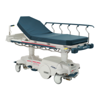
PNEUMATIC FOWLER ADJUSTMENT
Required Tools:
5/32” Hex Allen Wrench 1/2” Open End Wrench
1. Refer to the pneumatic Fowler assembly drawing on page 79 for parts reference.
2. For easier access, raise the Fowler to 75_ or higher.
3. Using a 1/2” open end wrench, loosen the hex nuts (item H) in the actuator arms on the end of the trip
bar (item B).
4. To adjust the Fowler, use a 5/32” hex Allen wrench to turn the Allen screws (item R) 1 to 2 turns count-
er−clockwise if the Fowler will not move or 1 to 2 turns clockwise if the Fowler will not hold its position.
5. Retighten the hex nuts. Be sure the Fowler travels from flat up to 90_ and down again and holds its posi-
tion when weight is applied before returning the stretcher to service.
Return to Table of Contents