BBrraakkee ccaamm aanndd lliinnkk rreeppllaacceemmeenntt
TToooollss RReeqquuiirreedd::
• Needle nose pliers
• Bungee cords
1. Raise the product to the highest position.
2. Raise both siderails to the up and latched position.
3. Raise the base hood and support the hood with bungee cords.
4. Put the brake/steer pedal in the neutral position.
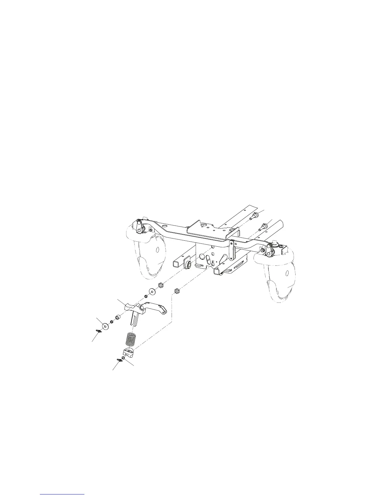
5. Using needle nose pliers, remove the rue ring cotter (A) and clevis pin (B) that secure the brake cam and link assembly
to the brake rod (Figure 4).
6. Using needle nose pliers, remove the rue ring cotter (C) and washer (D) from the bearing pivot support (E).
7. Using needle nose pliers, remove the rue ring cotter (G) and plastic washer (H) from the bottom support (F).
8. Raise the brake cam and link assembly (J) off of the brake rod actuator and pull outward on the assembly.
9. Reverse steps to reinstall.
NNoottee -- When you install the brake cam and link assembly, install the bottom first, and then push downward and inward
to install the assembly under the top bearing.
10.Verify proper operation before you return the product to service.
FFiigguurree 44 –– RReemmoovvee tthhee bbrraakkee ccaamm aanndd lliinnkk aasssseemmbbllyy
BBrraakkee rroodd rreeppllaacceemmeenntt
TToooollss RReeqquuiirreedd::
• 1/2” socket
• 3/8” drive torque wrench (ft-lb)
• 3/8” drive ratchet
EN 20
0747-109-002 Rev A.3