• Needle nose pliers
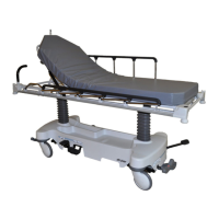
1. Raise the litter to the highest height.
2. Raise the base hood and support the hood with bungee cords.
3. Raise the siderails to the up and latched position.
4. Put the product into the steer position.
5. At the head end of the product, use needle nose pliers to remove the rue ring cotter (A) and clevis pin (B) that secure the
head end brake link assembly to the brake activation crank (Figure 5). Remove the brake rod crank cap. Save the rue
ring cotter, clevis pin, and brake rod crank cap.
6. Using needle nose pliers, remove the rue ring cotter (C) and clevis pin (D) that secure the brake cam and link assembly
to the brake rod assembly. Save the rue ring cotter and clevis pin.
7. At the foot end of the product, use needle nose pliers to remove the rue ring cotter (C) and clevis pin (D) that secure the
foot end brake link assembly to the brake activation crank. Remove the brake rod crank cap. Save the rue ring cotter,
clevis pin, and brake rod crank cap.
8. If the product is equipped with the four-sided brakes, proceed to step 9. If the product is equipped with the standard
brakes, proceed to step 10.
9. Using needle nose pliers, remove the rue ring cotter (E) and clevis pin (F) that secure the side control brake assembly to
the side control brake rod link. Save the rue ring cotter and clevis pin.
10.Using a 1/2” socket and a 3/8” drive ratchet, remove the non-self-tapping hex washer head screw (G) and sleeve
bearing that secure the fifth wheel drive link assembly to the brake rod assembly. Save the screw and sleeve bearing.
When you reinstall the screw, use a 3/8” drive torque wrench to torque the screw to 13 ± 2 ft-lb.
11.At the foot end of the product, use needle nose pliers to disconnect the return spring (H).
12.Using a 1/2” socket and a 3/8” drive ratchet, remove the four hex washer head screws (J) that secure the brake rod
supports to the brake rod assembly. Remove the return spring hook (K) (Figure 6). Save the screws and the return
spring hook. When you reinstall the hex washer head screws, use a 3/8” drive torque wrench to torque the screws to 13
± 2 ft-lb.
13.Reverse steps to install.
14.Verify proper operation before you return the product to service.
0747-109-002 Rev A.3
21 EN