-8-
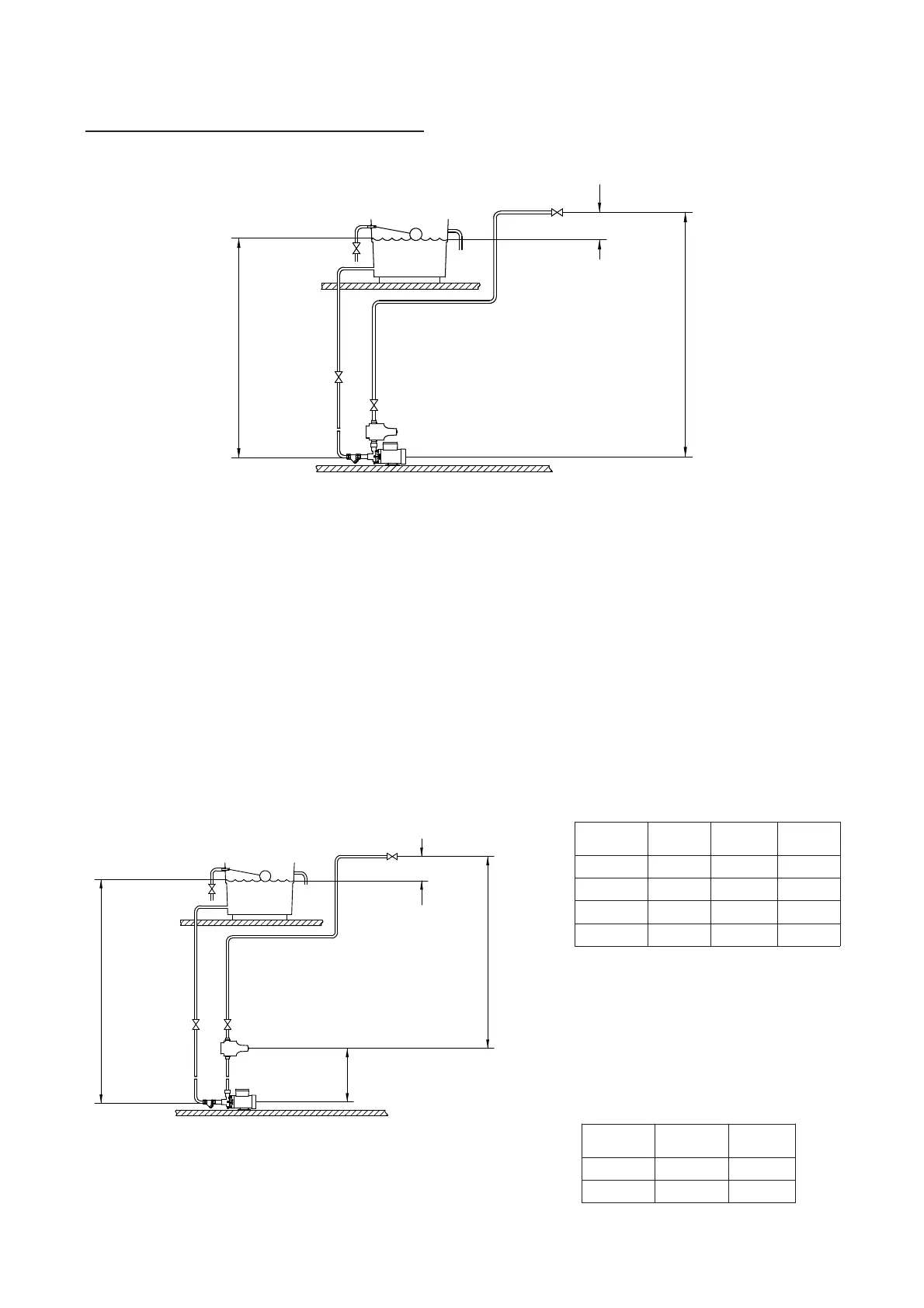
Pump Mounted Below Liquid Source (Flooded Suction Installation)
*Dimension ‘A’ (given above) is the
maximum distance the control module
can be repositioned when the static inlet
head is at the 1 metre minimum
requirement.
However dimension ‘A’ can be increased
to correspond with any increase in the
static inlet head eg:
Before deciding where to locate the unit, check to ensure the static inlet head (Fig. 4)
meets the minimum requirement of 1 metre and does not exceed the maximum given in
the limits of application section.
The static outlet head (Fig. 4) must also be within the maximum requirement of 8
metres for the KB6 model and 14 metres for all other models.
If the static outlet head exceeds the maximum permissible, the control module must be
re-located and consideration must be given to the maximum permitted distance the control
module can be moved (Fig. 5). No draw offs should be fitted between the control module
and the pump.
For details of removing the pressure control module from the pump and re-wiring,
consult the push-in fittings and electrical installation sections.
Diagram showing typical Boostamatic installation
with flooded suction and remote mounting of
pressure control module.
Fig. 5
Diagram showing typical Boostamatic installation
with flooded suction and pressure control module
mounted directly onto pump.
Fig. 4
Max. inlet head (consult limits of application section)
Min. inlet head 1 m
Negative
head
Max. outlet head 14 m (except KB6)
Max. outlet head 8 m (KB6 only)
Max. inlet head (consult limits of application section)
Min. inlet head 1 m
Negative
head
Max. outlet head 14 m
(except KB6)
Max. outlet head 8 m
(KB6 only)
*Dim. A
(see chart)
Model
Dim. ‘A’
(m)
Model
Dim. ‘A’
(m)
KB6 3 Jet 40 18
330 8 Jet 90 32
500 20 Loddon 29
600 31 Thame 12
Model
Inlet Head
(m)
Dim. ‘A’
(m)
500 1 20
500 5 24