-9-
Pump Mounted Above Liquid Source (Suction Lift Installation)
The pumps can be used in a suction lift installation providing the height of lift is within
the limits specified in the limits of application section and the liquid to be pumped is cold
water (for applications other than cold water contact Stuart Turner).
Before deciding where to locate the unit, check to ensure the static outlet head (Fig. 6)
does not exceed the maximum requirements of 8 metres for the KB6 model and 14
metres for all other models.
If the static outlet head does exceed the maximum permissible, the control module must
be re-located and consideration must be given to the maximum permitted distance the
control module can be moved (Fig. 7). No draw offs should be fitted between the control
module and the pump.
For details of removing the pressure control module from the pump and re-wiring,
consult the push-in fittings and electrical installation sections.
A footvalve and strainer must always be used and the suction pipework size must match
the pump.
Lay the suction piping over the shortest possible distance and ensure there is a
constant rise from the liquid source to the pump. Any high spots will cause air pockets to
form, reducing system efficiency.
Ensure all joints in suction pipework are completely airtight. Failure to comply will result
in loss of prime.
The intake of the footvalve/strainer should be positioned such that it cannot be blocked
with debris or silt that are frequently found in the bottom of sumps and wells.
When a footvalve is installed in the suction pipework, it is recommended that suitable
pressure relief valve be fitted in the discharge (outlet) pipework from the pump.
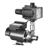
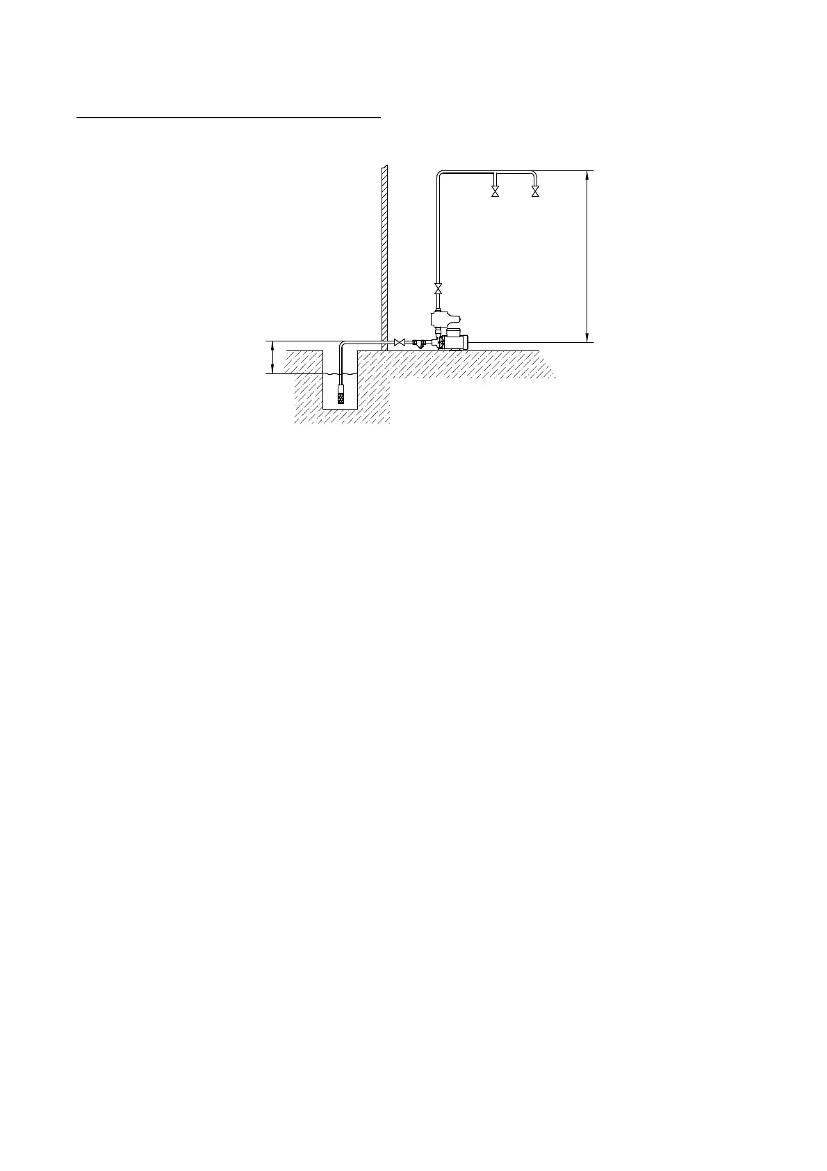
Diagram showing typical Boostamatic installation
with suction lift and pressure control module
mounted directly onto pump.
Fig. 6
Max. suctiion lift (consult limits of application section)
Max. outlet head 14 m
(except KB6)
Max. outlet head 8 m
(KB6 only)