D19 MasterSync
E 1/6 Come in! Date printed: 13.09.00
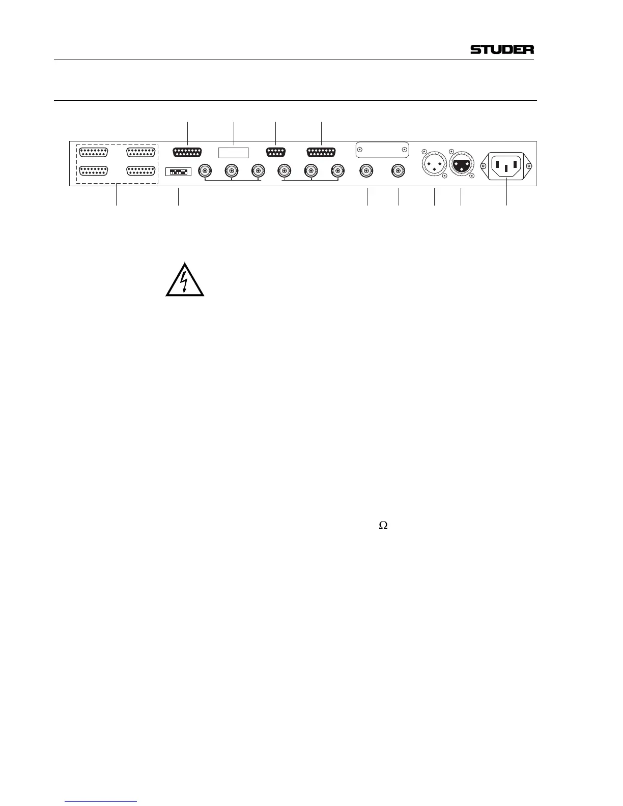
1.3.3 Connector Field
[1]
[6]
[3]
Mains~
100 240 V
OUT INVIDEOWCLK INWCLK OUT
ALARM REDUNDANCY LINK
AES IN AUX 1-4
DISTR MODE
AES IN 1-4AES OUT 5-8
AES OUT 13-16
AES OUT 1-4
AES OUT 9-12
[4]
[2]
[5][7][12]
[9] [10][11]
[1] Mains ~ 100 – 240 V Connector for socket IEC 320/C13.
Supply voltage range 100...240 V
AC
(without voltage selector);
mains frequency 50...60 Hz.
For connecting to the mains, please consult the Safety section at the
very beginning of this manual.
[2] AES IN 1-4 Inputs for four digital input signals according to AES/EBU, with a fe-
male 15-pin D-type connector.
[3] AES IN Input for sync signal with female XLR socket. Depending on the DIP
switch setting (see section 3.1), this input signal can be routed to the
outputs 1...4.
[4] AES OUT 1-... Outputs for 16 digital output signals according to AES/EBU, with four
male 15-pin D-type connectors.
[5] AES OUT Sync output with male XLR socket, hard-wired to the AES IN sync
signal input (XLR).
[6] VIDEO IN BNC socket.
[7] WCLK IN Word clock input, BNC socket, 75
W
termination jumper-selectable.
[8] WCLK OUT Word clock outputs, 6 BNC sockets.
[9] ALARM Alarm outputs watching the AES/EBU inputs 1...4 and the power sup-
ply; female 9-pin D-type connector.
[10] REDUNDANCY LINK Link socket for redundancy connection to a second unit, with female
15-pin D-type connector.
[11] AES IN AUX 1-4 Optional inputs for four redundant, digital input signals according to
AES/EBU, with a female 15-pin D-type connector.
[12] DISTR. MODE DIP switch bank with eight switches for basic settings, as routing se-
lection (refer to section 3.1).