D19 MasterSync
Operation E 2/3
Date printed: 13.09.00
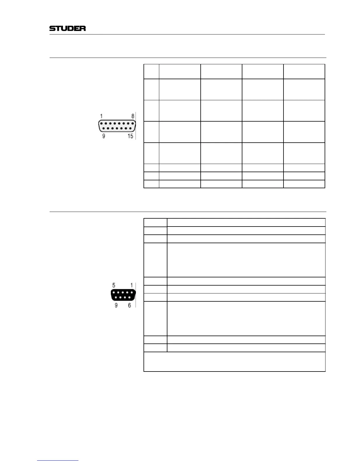
2.2.4 4 × 4 AES/EBU OUT (4 × 15-pin D-type, m)
Pin
Signal
(Out 1...4)
Signal
(Out 5...8)
Signal
(Out 9...12)
Signal
(Out 13...16)
1
9
2
AES 1a
AES 1b
Screen
AES 5a
AES 5b
Screen
AES 9a
AES 9b
Screen
AES 13a
AES 13b
Screen
10
11
3
Screen
AES 2a
AES 2b
Screen
AES 6a
AES 6b
Screen
AES 10a
AES 10b
Screen
AES 14a
AES 14b
15
7
14
AES 3a
AES 3b
Screen
AES 7a
AES 7b
Screen
AES 11a
AES 11b
Screen
AES 15a
AES 15b
Screen
6
5
13
Screen
AES 4a
AES 4b
Screen
AES 8a
AES 8b
Screen
AES 12a
AES 12b
Screen
AES 16a
AES 16b
4 n.c. n.c. n.c. n.c.
12 n.c. n.c. n.c. n.c.
8 n.c. n.c. n.c. n.c.
2.2.5 ALARM (9-pin D-type, f)
Pin Signal
1 24 V
2 GND
3 WARN relay contact output.
Active if an internal supply has a malfunction, provided that two units are
linked together or a second power supply unit is installed.
Depending on the jumper configuration, the relay connects (P25-P26) this pin
with pin 6 or interrupts (P26-P27) this connection.
4 Error signal AES IN 2 *
5 Error signal AES IN 4 *
6 WARN/FAIL common relay contact
7 FAIL relay contact output.
Active if the generator canot generate a valid AES/EBU signal in spite of
redundancy.
Depending on the jumper configuration, the relay connects (P22-P23) this pin
with pin 6 or interrupts (P23-P24) this connection.
8 Error signal AES IN 1 *
9 Error signal AES IN 3 *
* These signals are used only if the Redundancy option is installed. They are open-collector
signals pulling to GND in case of an error. The lines can be pulled to ground externally as well
for a forced switch-over to the Redundancy inputs.