D19 MasterSync
E 3/2 DIP switch and jumpers
Date printed: 13.09.00
3.2 Internal Jumpers
Caution: All internal adjustments as well as repair work on this product must be
performed by a trained technician – no user-serviceable parts inside!
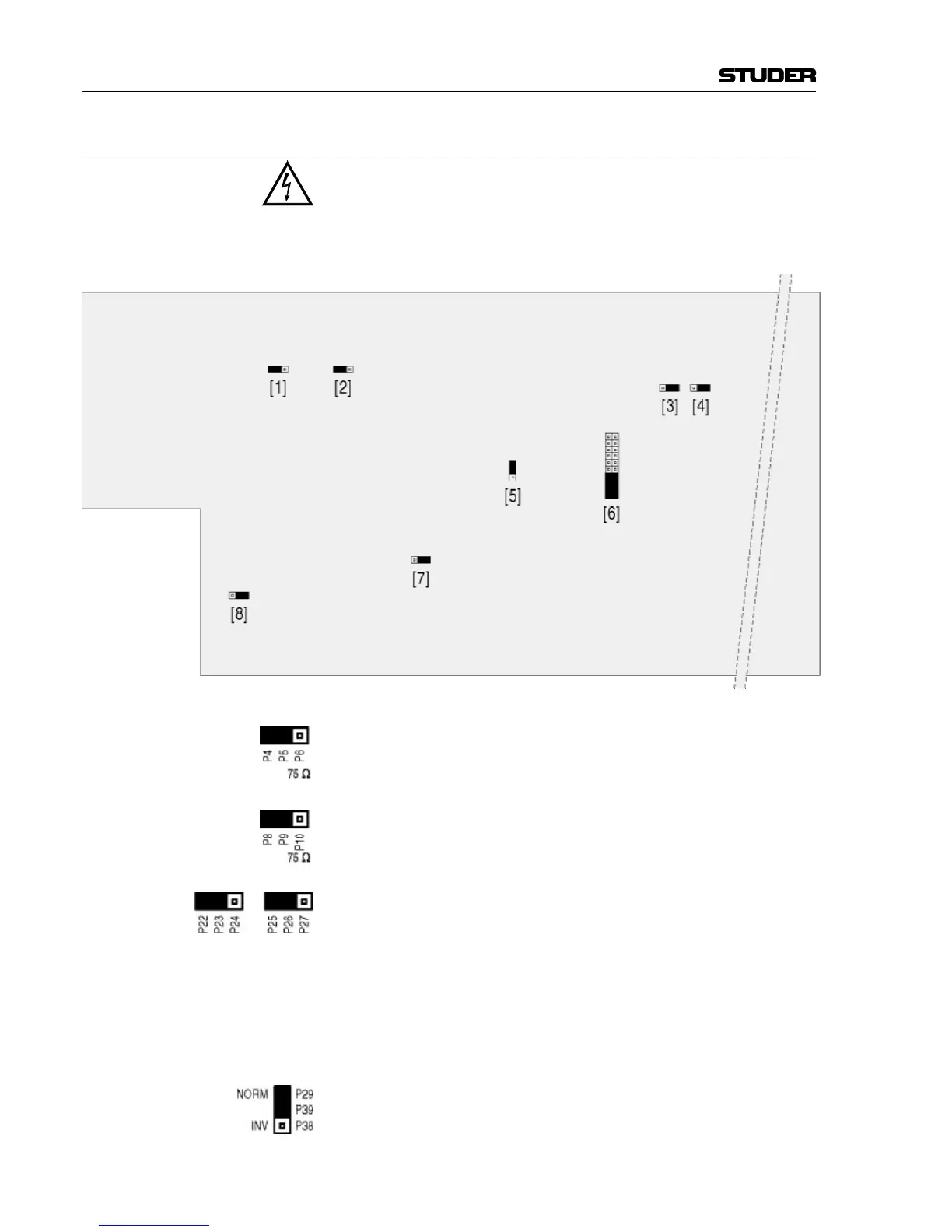
Factory setting: In all drawings below, the default jumper settings are marked in black.
[1] Impedance setting for the VIDEO input (BNC socket).
Default setting: hi-Z.
[2] Impedance setting for the WCLK IN input (BNC socket).
Default setting: hi-Z; when changing the jumper to position P9-P10,
the input impedance is 75 Ω.
[3], [4] Configuration for the FAIL and WARN relay contact outputs.
FAIL is active if the generator cannot generate a valid AES/EBU signal
in spite of redundancy. Jumper set to P22-P23: Make contact (default
setting); jumper set to P23-P24: Break contact.
WARN is active if an internal supply has a malfunction, provided that
two units are linked together or a second power supply unit is installed.
Jumper set to P25-P26: Make contact (default setting); jumper set to
P26-P27: Break contact.
[5] Polarity inversion of the word clock outputs 4...6 if jumper is set to
INV (i.e. P38-P39); Default setting: NORM (P29-P39).