D19 MasterSync
DIP switch and jumpers E 3/1
Date printed: 13.09.00
3 DIP SWITCH AND JUMPERS
3.1 DIP Switch Settings
The DIP switch is located at the rear of the unit and is accessed through
a hole in the rear panel. The switches are numbered 1...8 from the left
to the right.
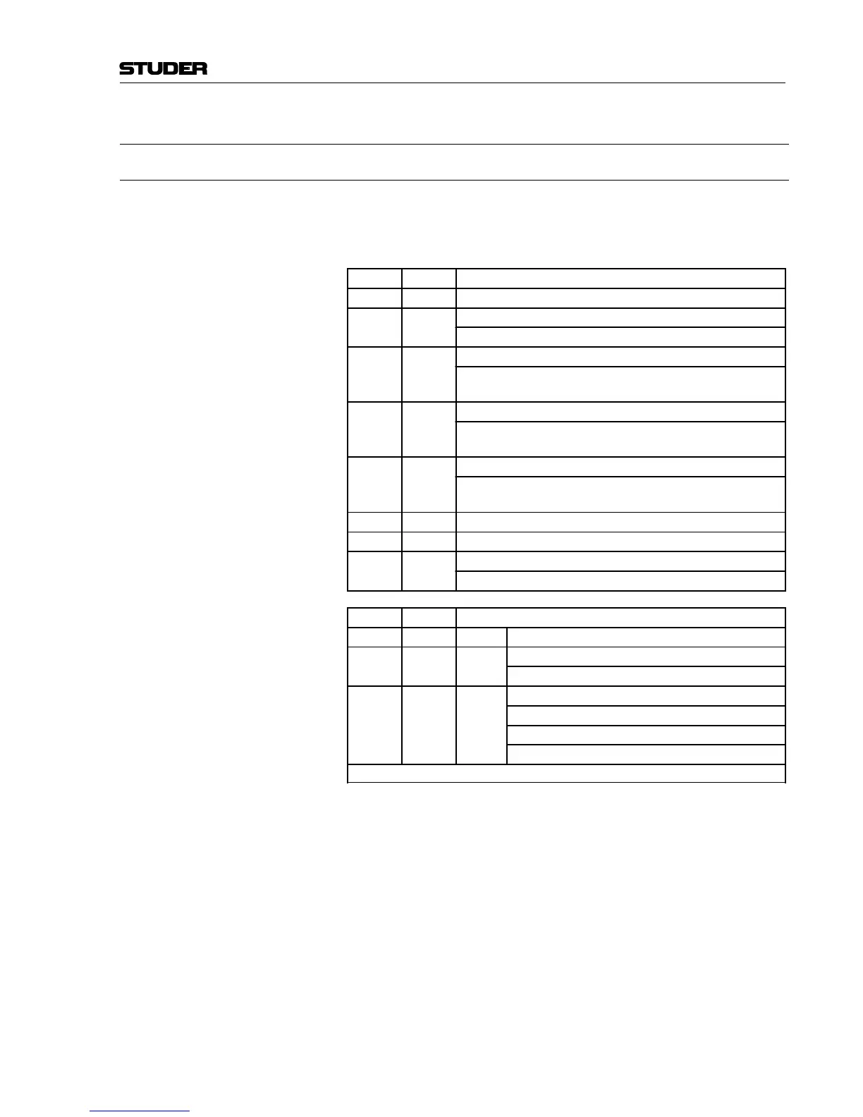
Switch Signal Explanation
1 spare -
2 IINT1 ON: AES OUT 1...4 routed to SYNC generator
OFF: AES OUT 1...4 routed to AES IN 1
3 IINT2 ON: AES OUT 5...8 routed to SYNC generator
OFF: AES OUT 5...8 routed to AES IN 1 or 2 (depending on DIP
switches 6 and 7)
4 IINT3 ON: AES OUT 9...12 routed to SYNC generator
OFF: AES OUT 9...12 routed to AES IN 1 or 3 (depending on DIP
switches 6 and 7)
5 IINT4 ON: AES OUT 13...16 routed to SYNC generator
OFF: AES OUT 13...16 routed to AES IN 1, 3, or 4 (depending on
DIP switches 6 and 7)
6 DESW0 see table below
7 DESW1 see table below
8 IINTWCL ON: Word clock outputs routed to the internal generator
OFF: Word clock outputs routed to the word clock input directly
DESW0 DESW1 Explanation
ON ON 1 to 16: AES IN 1 routed to AES OUT 1...16 *
OFF ON 2 to 8: AES IN 1 routed to AES OUT 1...8
AES IN 3 routed to AES OUT 9...16 *
ON OFF 4 to 4: AES IN 1 routed to AES OUT 1...4
AES IN 2 routed to AES OUT 5...8
AES IN 3 routed to AES OUT 9...12
AES IN 4 routed to AES OUT 13...16 *
* Valid if none of the IINTx signal switches 2...5 (above) is set to ON