EN/07.2013/58/11
DI9 A13 Free contact X36 pin 1
X36 pin 2 Low pressure input
DI10 A2 Free contact X34 pin 1
X34 pin 2 Humidity switch
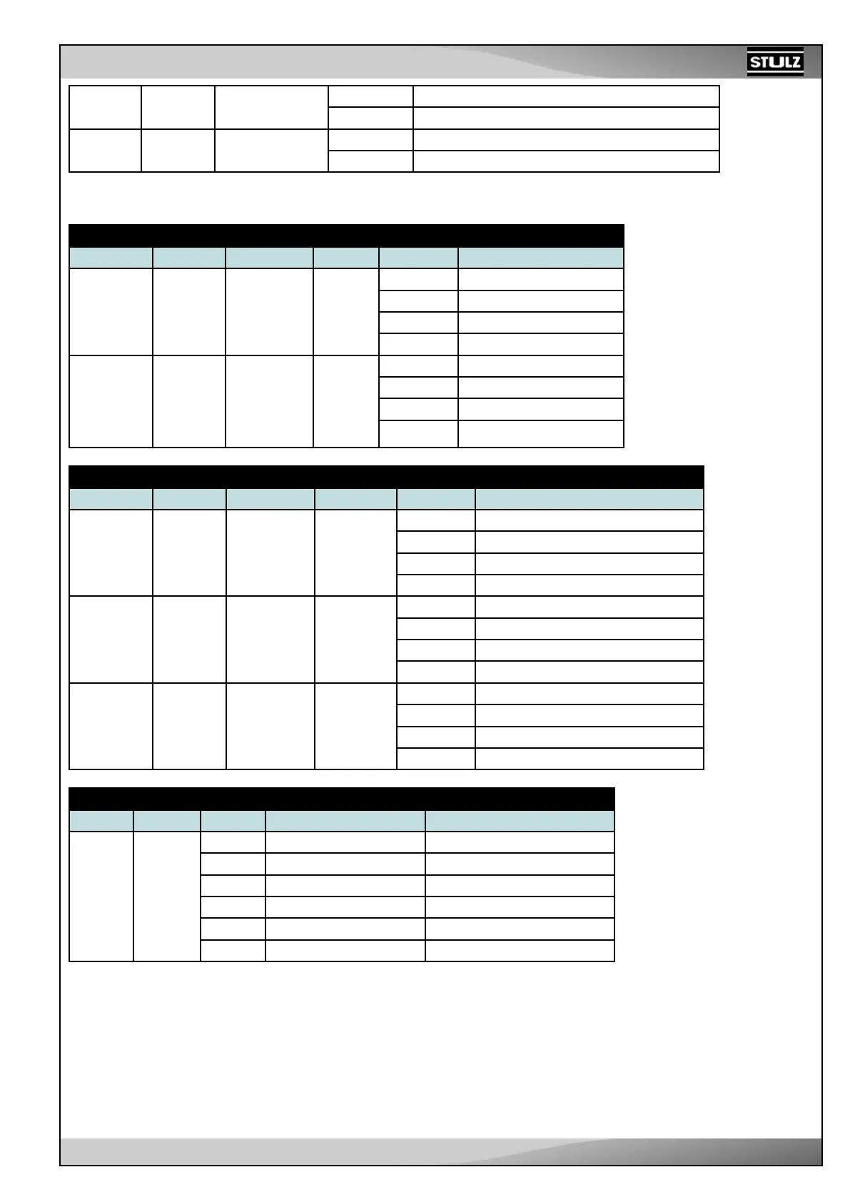
Analog output
ANALOG OUTPUT
Name Logic ID Signal type Range Terminals Features - description
ANOUT1 DAC0 Vdc 0÷10 V X6 pin 1 DC 1 supply : positive
X6 pin 2 DC 1 supply : negative
X6 pin 3 0÷10V signal output
X6 pin 4 Signal reference
ANOUT2 DAC1 Vdc 0÷10 V X7 pin 1 DC 2 supply : positive
X7 pin 2 DC 2 supply : negative
X7 pin 3 0÷10V signal output
X7 pin 4 Signal reference
DC FANS
Name Logic ID Signal type Range Terminals Features - description
V1 V1 PWM Duty cycle
0÷100 %
X17 pin 1 Fan 1 supply: positive
X17 pin 2 Fan 1 supply: negative
X17 pin 3 Fan 1 - PWM Signal (f = 1 kHz)
X17 pin 4 Fan 1 - Tachometric Signal input
V2 V2 PWM Duty cycle
0÷100 %
X18 pin 1 Fan 2 supply: positive
X18 pin 2 Fan 2 supply: negative
X18 pin 3 Fan 2 - PWM Signal (f = 1 kHz)
X18 pin 4 Fan 2 - Tachometric Signal input
V3 V3 PWM Duty cycle
0÷100 %
X19 pin 1 Fan 3 supply: positive
X19 pin 2 Fan 3 supply: negative
X19 pin 3 Fan 3 - PWM Signal (f = 1 kHz)
X19 pin 4 Fan 3 - Tachometric Signal input
AC FANS OUTPUT FOR SPEED ADJUSTMENT - PHASE CUT
Name Logic ID Pin (X8) Type Function description
AC FAN VC 1 Line Input: Phase Condenser fan
2 Phase cut Output
3
4 Line Input: Neutral 230 Power supply
5 Line Output: Neutral
6
An auxiliary connector (X25) is provided on board, in order to control the phase-cut module. The signal is a 5 mA
(approximately) current pulse on a 1K load; in order to produce the right phase delay between the pulse and the
network voltage zero-crossing instant, the line has to be connected necessarily to the poles 1 and 4 of X8.