EN/07.2013/58/31
3.4.6. I/O Setup
As the I/O SETUP is selected, the password is requested to get access to this parameter list.
After typing the correct password, the display will show the following mask.
I/O SETUP Iyy
XXXX
XXXX
CURRENT VALUE
The second and the third line of the display are on the MASK column of the following list of parameters.
In the first line is indicated the type of setup menu, I/O SETUP in this case, and at the corner the IdCode of the
parameter. The fourth line shows the current value of the displayed parameter.
Use the UP/DOWN ARROW keys to scroll all the parameters.
IMPORTANT NOTE: After changed the I/O SETUP is necessary to turn off and turn on the board. If this operation is not
done, the behaviour of the system can be unpredictable.
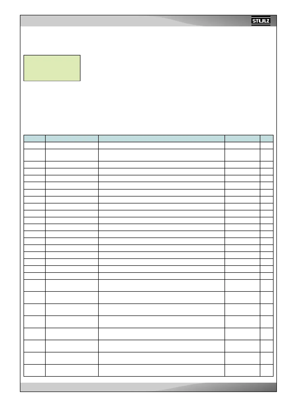
IdCode MASK Description Range Unit
PASSWORD Necessary to enter the following parameters
I 01.
Unit configuration
Right=0 Left=1
Parameter for change the analog input and the logical for the
damper motor
0/1
I02. Channel offset T1 Offset of the channel T1. Default: TE -99.9/99.9°C °C/F
I03. Channel offset T2 Offset of the channel T2. Default: TI -99.9/99.9°C °C/F
I04. Channel offset T3 Offset of the channel T3. Default: TC -99.9/99.9°C °C/F
I05. Channel offset T4 Offset of the channel T4. Default: TAE -99.9/99.9°C °C/F
I06. Channel offset IC1 Offset of the channel IC1. Default: IRH -99.9/99.9 %
I07. Channel offset IC2 Offset of the channel IC2. Default: PC -99.9/99.9 Bar
I08. Channel offset IC3 Offset of the channel IC3. Default: ERH -99.9/99.9 -
I09. 4mA value for An-In IC1 4mA value for the channel IC1. Default: IRH *value at 4 mA -99.9/99.9 %
I10. 20mA value for An-In IC1 20mA value for channel IC1. Default: IRH *value at 20 mA -99.9/99.9 %
I 11. 4mA value for An-In IC2 4mA value for channel IC2. Default: PC *value at 4 mA -99.9/99.9 Bar
I12. 20mA value for An-In IC2 20mA value for channel IC2. Default: PC *value at 20 mA -99.9/99.9 Bar
I13. 4mA value for An-In IC3 4mA value for channel IC3. Default: ERH *value at 4 mA -99.9/ 99.9 -
I14. 20mA value for An-In IC3 20mA value for channel IC3. ERH *value at 20 mA -99.9/ 99.9 -
I15. 0V value for An-Out1 0V value for channel AnOut1. 0 /100 %
I16. 10V value for An-Out1 10V value for channel AnOut1. 0 /100 %
I 1 7. 0V value for AnOut2 0V value for channel AnOut2. 0 /100 %
I18. 10V value for AnOut2 10V value for channel AnOut2. 0 /100 %
I19.
Analog channel Linked
to IC1
Name of the Analog channel linked to the physical analog input1 See table below -
I20.
Analog channel Linked
to IC2
Name of the Analog channel linked to the physical analog input2 See table below -
I21.
Analog channel Linked
to IC3
Name of the Analog channel linked to the physical analog input3 See table below -
I22.
Analog channel Linked
to T1
Name of the Analog channel linked to the physical analog input4 See table below -
I23.
Analog channel Linked
to T2
Name of the Analog channel linked to the physical analog input5 See table below -
I24.
Analog channel Linked
to T3
Name of the Analog channel linked to the physical analog input6 See table below -
I25.
Analog channel Linked
to T4
Name of the Analog channel linked to the physical analog input7 See table below -
I26.
Select Relay Evaporator
Fan
Select the relay linked to evaporator fan
R3-R13/No
conn
-