35
➊
➋
➌
➍
➎
➏
➐
➑
➒
➊
➋
➌
➍
➎
➏
➊
➋
➌
➍
➎
➏
➐
BA C7000 for EC Tower | EN | 01-2019 | 1000755
Config
Components/Air
Fan/...
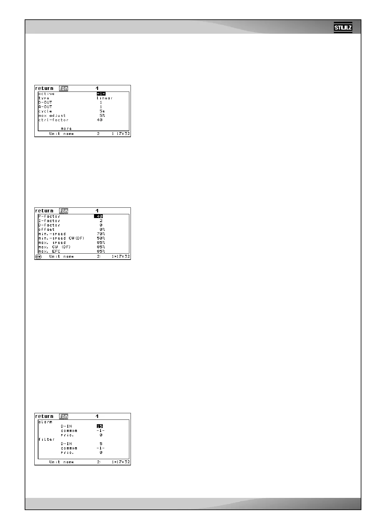
You add a fan to the configuration by setting the “ACTIVE” parameter to 1. You deacti-
vate the fan with “0”. ➊
You define the fan type in the following lines (2 step: fan with on/off control, linear: EC
fan with proportional speed regulation). ➋
You determine the digital output for an on/off fan using the “D-OUT” parameter ➌. The ap-
proval signal is outputted via this output in the case of a fan with proportional regulation.
You determine the analog output of the proportional signal for the EC fan using the
“A-OUT” parameter. ➍
The parameters:
- control interval (CYCLE) ➎
- max. control change ➏
- control factor ➐
are required for the DFC control and for the differential pressure control. Using this
parameter, the behavior of an integral control can be reproduced. For the DFC control,
see the “GE systems” instruction manual.
The P factor ➊, I factor ➋ and D factor ➌ for the control behavior can be adjusted in
the first lines of the subsequent menu. These three parameters exclusively apply to
the differential temperature control (Differential temperature control is not active on
the EC tower).
The offset is used to adapt the cooling air pattern to unexpected conditions on the site
(lower/higher pressure drop).➍
The minimum speeds, which you can adjust in lines 5 and 6, can only be bypassed
using the setting under “REDUCE SPEED”. The maximum speeds should be adjusted
according to the required layout air flow.
The minimum speed ➎ in line 5 and the maximum speed ➐ in line 7 apply to all units
except for CW operation in dual-fluid units.
The minimum speed CW(DF) ➏ in line 6 and the maximum speed ➑ in line 8 apply to
CW operation in dual-fluid units.
For dual-fluid units, the speed selection depends on the cooling priority. If there is a
fault change-over, the other speed is chosen. See page 28 for an exact description of
the conditions for a fault change-over.
The “max. EFC” parameter➒ is only required for the DFC control and not for the EC
tower.
Fan type:
Type 1: On/Off control
Type 2: Proportional regulation
.../general
.../general/more
.../Alarm
Alarm parameters:
Airflow alarm digital input ➊
Common alarm actuation ➋
Alarm priority ➌
Filter alarm digital input ➍
Common alarm actuation ➎
Alarm priority ➏
The alarms are handled in a special way in units
that have 3 fans configured. The speed of the
two remaining fans is increased to 100 % when
one fan malfunctions. The third fan is switched
off if two fans malfunction.
Note on the maximum speed ➐
Entering the maximum speed ➐ of the fan is necessary in order to establish the nec-
essary airflow.
The maximum speed ➐ is meant for reaching the speed required for reaching the
nominal airflow. This depends on the external pressure. Find the standard values on
the wiring diagram data sheet.
Example:
U
S
= 7.9 V corresponds with a maximum speed of 79 %.
(U
S
: voltage of the control signal)
The figure shows the parameters for
the EC tower
The figure shows the parameters for
the EC tower