7-58
Component Access / Removal
Built-In
Built-In
(600-
(600-
2
2
)
)
Series
Series
#3758407 - Revision B - August, 2006
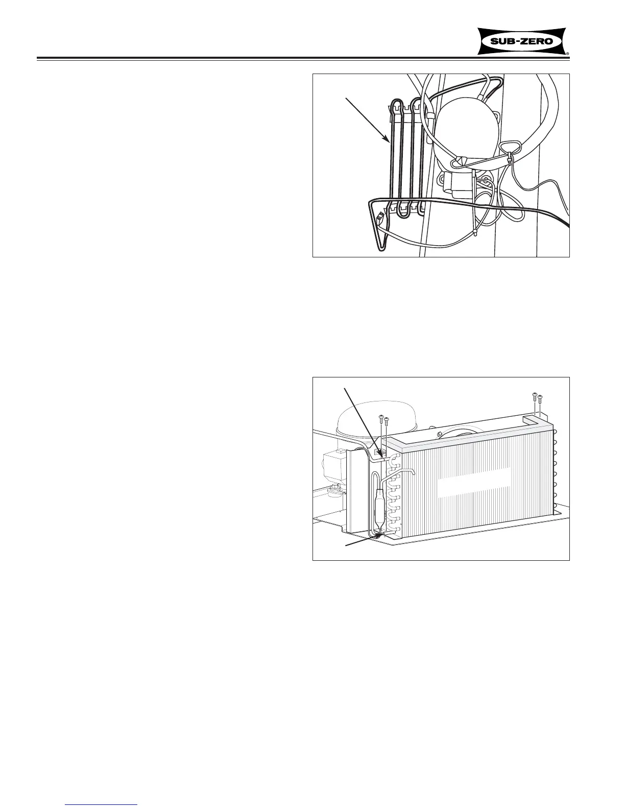
Drain Pan Condensate Heater Loop
(601R-2, 601RG-2)
The drain pan condensate heater loop is located in the
compressor area, and sits in the drain pan.
NOTE: When replacing a condensate heater loop, the
filter-drier must also be replaced.
NOTE: It is recommended that a suction line drier be
added to the sealed system when replacing the con-
densate heater loop.
After capturing the refrigerant from sealed system, (See
Figure 7-152):
1. Extract bolts from grommets at each corner of com-
pressor base.
2. Pull compressor forward and rotate to gain access
to condensate heater tubing.
3. Using a tube cutter, cut condensate loop inlet and
outlet.
NOTE: It is not recommended to sweat tubing apart.
Doing so will induce moisture into the sealed system.
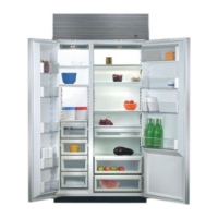
Condenser (601R-2, 601RG-2, 601F-2)
NOTE: When replacing the condenser, the filter-drier
must also be replaced.
After capturing the refrigerant from sealed system, (See
Figure 7-153):
1. Extract screws which hold condenser fan shroud to
condenser.
2. Using a tube cutter, cut condenser inlet and outlet.
NOTE: It is not recommended to sweat tubing
apart. Doing so will induce moisture into the sealed
system.
3. Extract condenser mounting screws which hold
condenser side brackets to unit tray.
4. Slide condenser to the right, then pull forward.
Figure 7-152. Drain Pan Condensate Heater Loop
Heater
Loop
Compressor
Figure 7-153. Condenser
Cut
Cut
Condenser