Built-In
Built-In
(600-
(600-
2
2
)
)
Series
Series
Electronic Control System
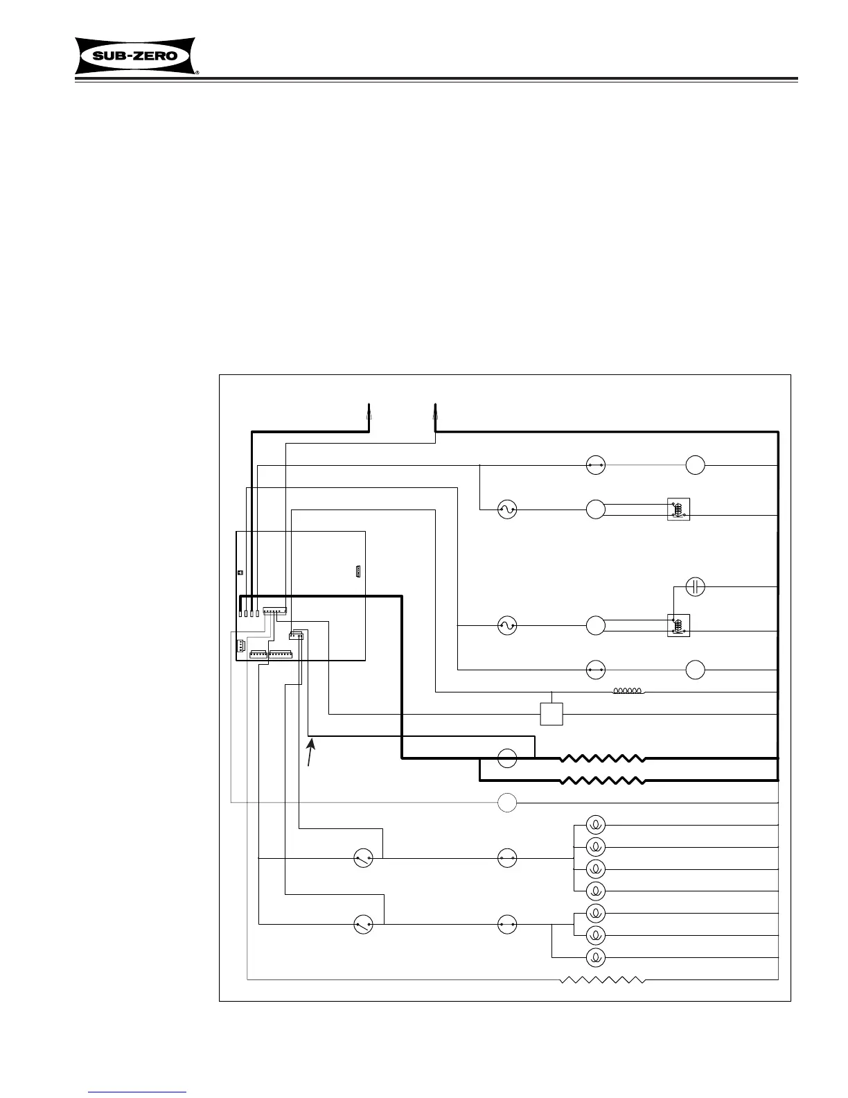
Monitor and Control “Adaptive Defrost” of Freezer Evaporator
Initially, the freezer compressor cycle-runs 12 hours. The control board defrost relay is then closed, supplying power
to the defrost, drain tube and fill tube heaters. The compressor, condenser fan and evaporator fan are switched off.
With “Adaptive Defrost”, the length of time the defrost heater stays on to open the defrost terminator bimetal
(55°F/13°C), is observed by the microprocessor via the grey w/white stripe wire to J4. This length of time is used to
calculate the number of hours before the next defrost (defrost interval). If the heater then stays on for a shorter time
period, the microprocessor increases the next defrost interval. If the heater then stays on for a longer time period,
the microprocessor decreases the next defrost interval. (See Figure 3-16) This is an ongoing process whereby the
defrost time and the defrost interval will vary by unit use.
NOTE: A 5 minute time delay/dwell follows all defrosts, during which the drain tube and fill tube heaters remains
energized. At the end of the 5 minute dwell, the compressor, evaporator fan and condenser fan are energized, and
the drain tube heater is switched off.
NOTE: Minimum defrost interval = 6 hours of compressor run time; Maximum defrost interval = 80 hours of com-
pressor run time; Maximum defrost duration = 20 minutes, plus 5 minute dwell.
NOTE: If the defrost
sensing line is open,
defrost operation
defaults to 25 minute
defrost time / 6 hour
build time, and Error
Code 22 is logged. If
the evaporator ther-
mistor detects an
under-heat or over-
heat situation at the
same time, Error
Codes 20 or 23 is
logged, respectively.
NOTE: During
defrost, the displayed
temperature is
locked.
Figure 3-16. Signal Trace Schematic of Freezer Adaptive Defrost
defrost sense line.
until 5 minutes after defrost.
code will be logged.