Sealed System Information
Built-In
Built-In
(600-
(600-
2
2
)
)
Series
Series
4-4
#3758407 - Revision B - August, 2006
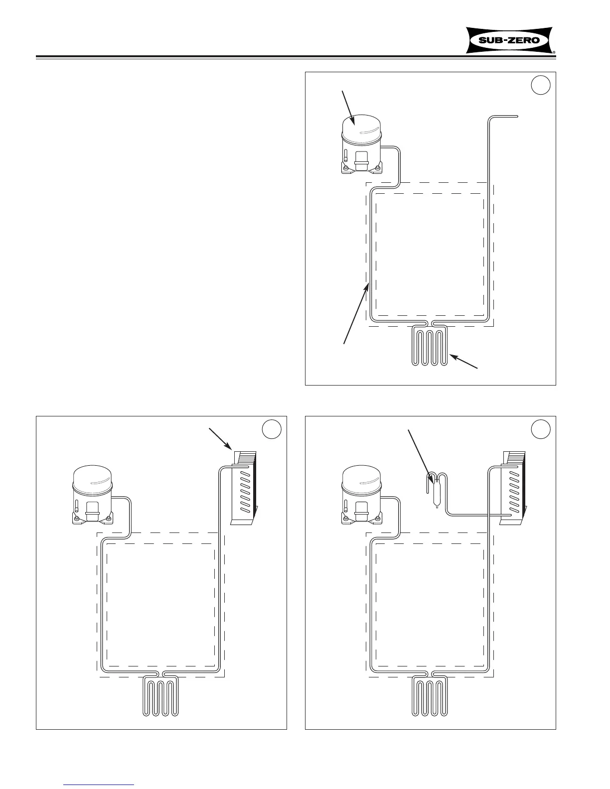
Figure 4-1. Compressor
1
3
Figure 4-2. Condenser
2
SEALED SYSTEM OPERATION
The following six diagrams illustrate a basic sealed sys-
tem. The components are listed in order of refrigerant
flow, with an explanation of their fundamental role as part
of a sealed system. NOTE: These illustrations do not
represent any specific 600-2 Series sealed system.
Compressor (Figure 4-1)
The compressor creates a high side and low side pres-
sure difference in the sealed system by compressing the
refrigerant gas, thus raising the pressure and tempera-
ture. The compressor pushes this high-pressure/high-
heat gas through the door gasket seat heater loop to pre-
vent sweating (on most units the gas also travels through
drain pan heater tubing to help evaporate water in the
drain pan). The high-pressure/high-heat gas then travels
to the condenser.
Condenser (Figure 4-2)
The high-pressure/high-heat gas travels through the con-
denser, where the heat is dissipated by cooler air being
drawn over the condenser tubing by the condenser fan.
This changes the gas into a high-pressure/warm liquid
that then enters the high-side filter-drier.
High-Side Filter-Drier (Figure 4-3)
The high-pressure/warm liquid travels through the high-
side filter-drier, which removes moisture from the refriger-
ant before it enters the capillary tube.
Compressor
Drain Pan
Heater Tubing
Door Gasket
Seat Heater
Loop
Condenser
High-Side Filter-Drier
Figure 4-3. High-Side Filter-Drier