Icemaker Information
Integrated
Integrated
(700-
(700-
3
3
T
T
ALL)
ALL)
Series
Series
6-8
#3758412 - Revision B - December, 2006
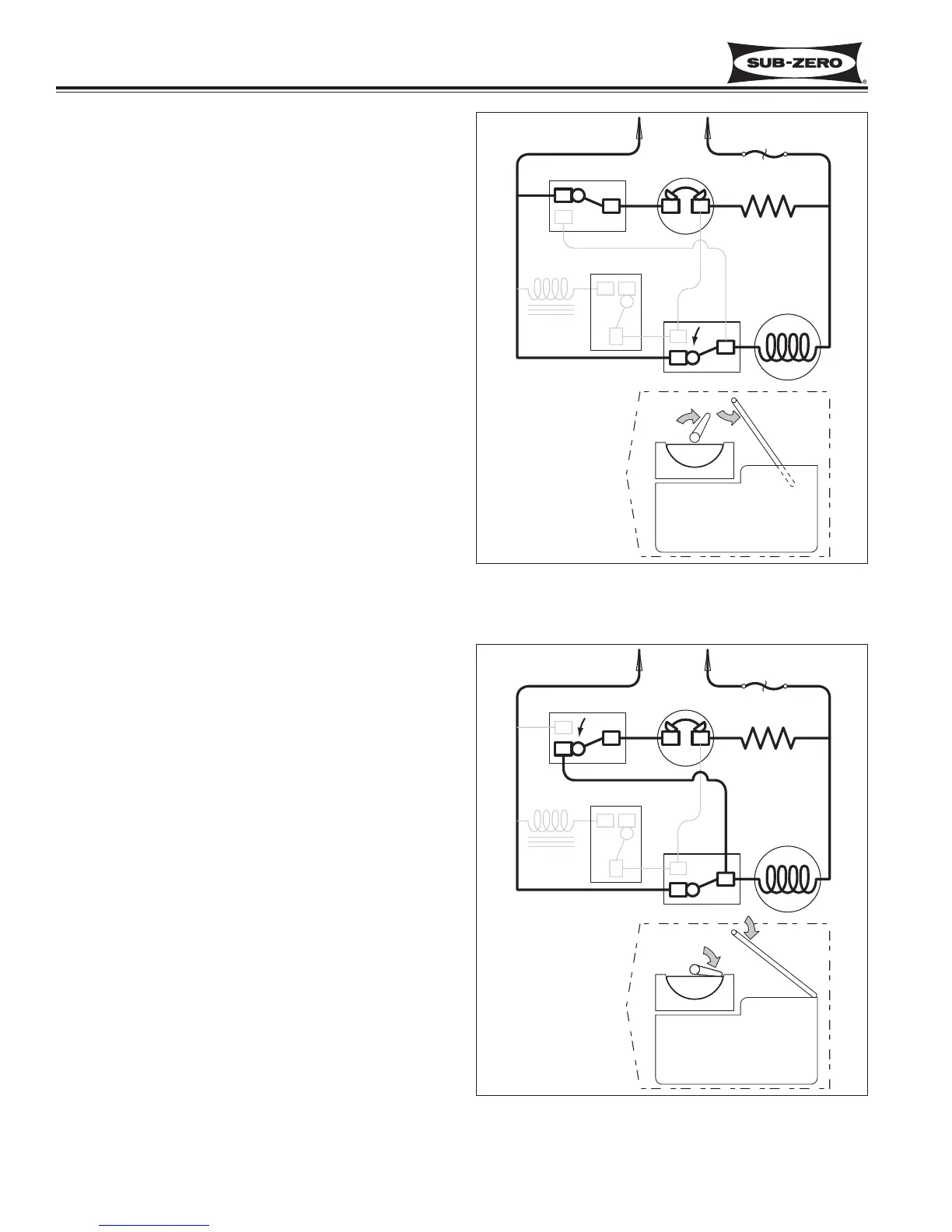
Figure 6-10. First Revolution Continued
First Revolution Continued (See Figure 6-10)
• The holding switch is tripped by the timing cam to
“normally open” thus holding power to the motor.
• The mold heater remains energized through the
thermostat.
• The shut-off arm begins to rise.
First Revolution Continued (See Figure 6-11)
• The ice ejector reach the ice in the mold.
• The ice releases from the mold as the ejector
blades begin to rotate the cubes out.
• The drive motor remains energized through the
holding switch.
• The mold heater remains energized through the
thermostat.
• As the shut-off arm rises, the shut off switch is
tripped to “normally closed”, and then the shut-off
arm begins to lower.
Figure 6-11. First Revolution Continued