Integrated
Integrated
(700-
(700-
3
3
T
T
ALL)
ALL)
Series
Series
Icemaker Information
6-9
#3758412 - Revision B - December, 2006
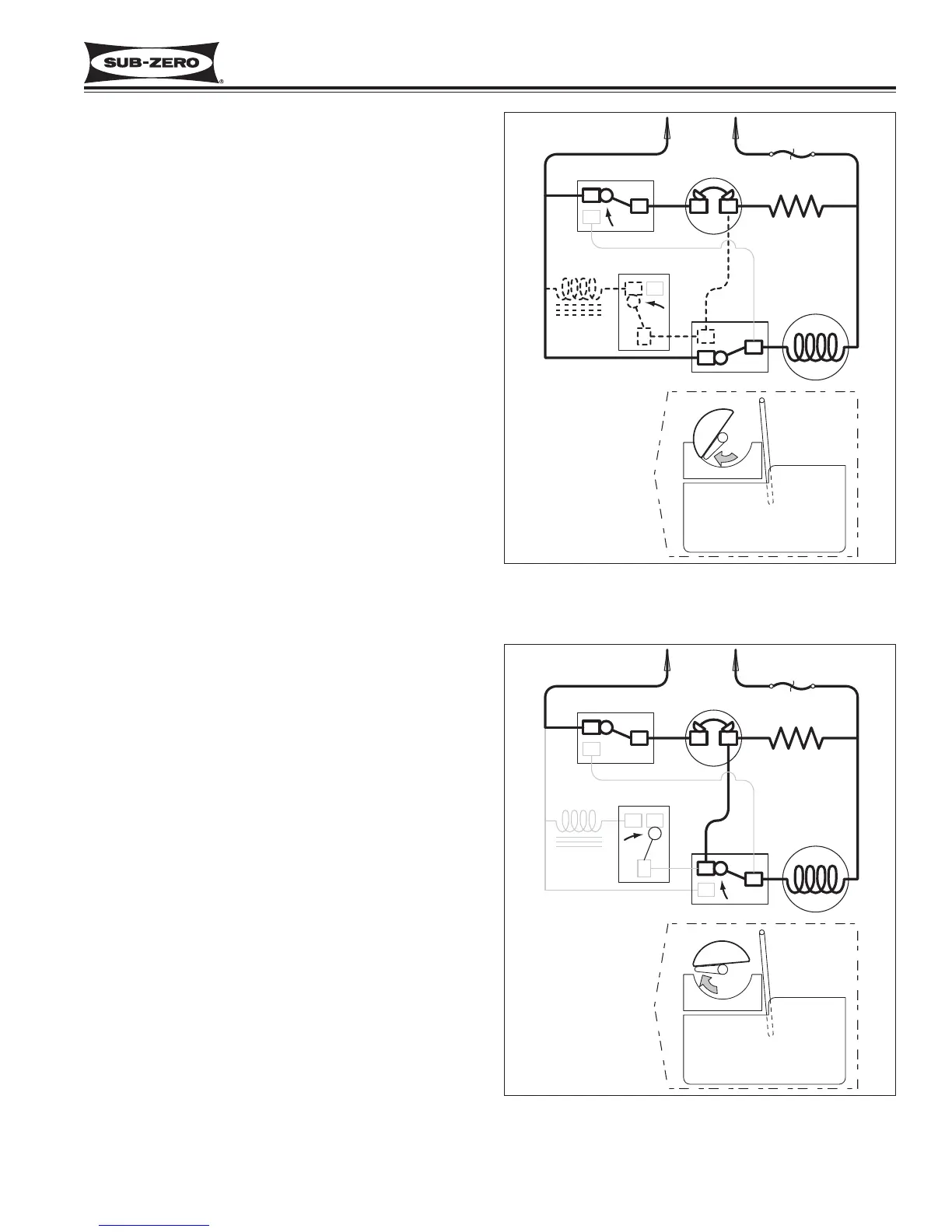
Figure 6-12. First Revolution Continued
First Revolution Continued (See Figure 6-12)
• The ice has released from the mold.
• The motor remains energized through the holding
switch.
• The shut-off arm is lowered and the shut off switch
is tripped to “normally open”.
• The water valve solenoid switch is tripped by the
timing cam, but the solenoid is not energized
because the thermostat is still closed and energiz-
ing the mold heater. (Electric current follows the
path of least resistance.)
End of First Revolution (See Figure 6-13)
• The water valve solenoid switch is tripped by the
timing cam back to “normally open.”
• The timing cam trips the holding switch to “normally
close,” which ends the first revolution, but the ther-
mostat is still closed, so the motor is again started.
• The mold heater remains energized through the
thermostat.
Figure 6-13. End of First Revolution