Icemaker Information
Integrated
Integrated
(700-
(700-
3
3
T
T
ALL)
ALL)
Series
Series
6-10
#3758412 - Revision B - December, 2006
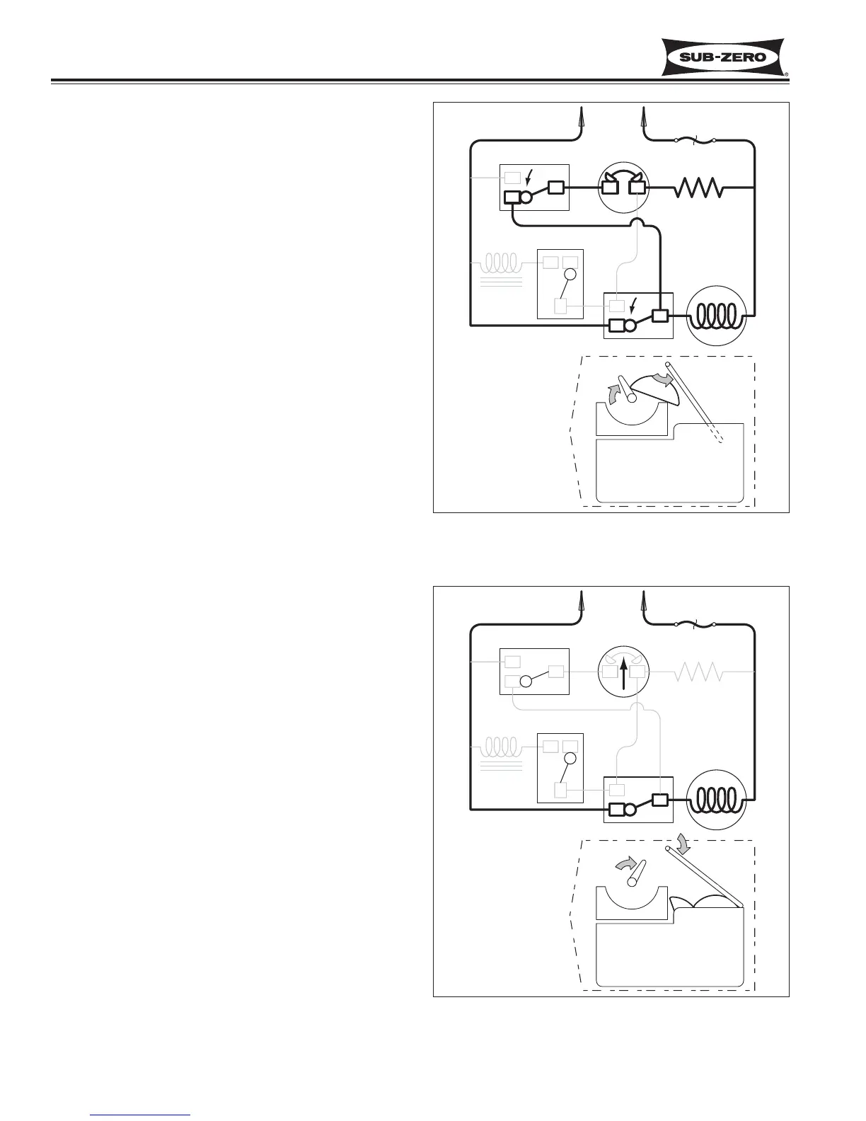
Figure 6-14. Start of Second Revolution
Start of Second Revolution (See Figure 6-14)
• The water valve solenoid switch is tripped by the
timing cam back to “normally open.”
• The timing cam trips the holding switch to “normally
close,” which ends the first revolution, but the ther-
mostat is still closed, so the motor is again started.
• The mold heater remains energized through the
thermostat.
Second Revolution Continued (See Figure 6-15)
• The mold heater has warmed the thermostat, so the
thermostat opens, and the mold heater is de-ener-
gized.
• If the shut-off arm comes to rest on top of the ice in
the storage bin (as illustrated), so the shut-off
switch will remain in the “normally closed” position.
• The motor remains energized through the holding
switch.
Figure 6-15. Second Revolution Continued