37
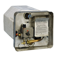
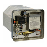
REPLACEMENT PARTS LIST FOR MODELS
SW10D, SW10DE, SW12D, SW12DE, SW16D, SW16DE
Item Part Number
No. Description SW10D SW10DE
SW12D SW12DE
SW16D SW16DE
1 Foam Jacket Assembly Complete (SW10D, SW10DE) ...................................................... 520869 520869
Foam Jacket Assembly Complete (SW12D, SW12DE) ...................................................... 520960 520960
Foam Jacket Assembly Complete (SW16D, SW16DE) ...................................................... 520961 520961
2 Switch, Lamp and Plate Assembly .................................................................................... 232589 232589
3 Module Board ...................................................................................................................... 520814 520814
5 Cover Module Board ........................................................................................................... 090487 090487
6 Bushing, Snap ½” ................................................................................................................ 070270 070270
7 Bushing, Strain Relief 5/8” .................................................................................................. 230216 230216
8 Nut 10-24 Keps (Green) ...................................................................................................... 121576 121576
9 Bushing, Snap 7/8” .............................................................................................................. ---------- 230218
11 Cover, Junction Box ............................................................................................................ ---------- 090576
12 D.C. Junction Box Assembly ............................................................................................... 090517 090517
15 Flue Collector Back Assembly Complete ............................................................................ 101777 101777
17 Screw 10 x 1/4 (3 Required) ............................................................................................... 121577 121577
18 Valve, Pressure Relief ......................................................................................................... 161157 161157
20 Gasket, Thermostat Cover .................................................................................................. 070987 070987
21 Cover, Thermostat/Hi-Limit .................................................................................................. 090562 090562
23 Bracket, Electrode Mounting ............................................................................................... 063187 063187
24 Grommet ............................................................................................................................. 070874 070874
25 Electrode ............................................................................................................................. 232258 232258
27 Burner Assembly with orice ............................................................................................... 010843 010843
29 1/4 Loxit Nut (Manifold to Valve) ......................................................................................... 171463 171463
31 Cover, Element .................................................................................................................... ---------- 090445
32 Gasket Element Cover ........................................................................................................ ---------- 070988
33 Bushing, Snap ½” ................................................................................................................ ---------- 070270
34 Anode .................................................................................................................................. 232767 232767
35 Grommet, Gas Inlet ............................................................................................................. 070989 070989
36 A.C. Junction Box Assembly ............................................................................................... ---------- 090575
37 Switch Assembly 120 V.A.C. T-Stat/Hi-Limit ....................................................................... ---------- 232306
38 Switch Assembly 12 V.D.C. T-Stat/Hi-Limit ......................................................................... 232282 232282
40 Grommet ............................................................................................................................. 071246 071246
42 Switch, Electric Element ...................................................................................................... ---------- 232362
44 Gas Fitting ........................................................................................................................... 170374 170374
45 Electric Element with Gasket............................................................................................... ---------- 520789
46 Valve, Gas (LP) ................................................................................................................... 161109 161109
47 Manifold Outlet .................................................................................................................... 171420 171420
48 Valve Mounting Bracket ...................................................................................................... 063243 063243
49 Screw 8-32 x 3/8 Hex HD (2 Required) ............................................................................... 121958 121958
51 Burner Bracket ................................................................................................................... 063444 063444
52 Screw 8mm - 4.0 x ½ Hex Washer Head (2 Required) ....................................................... 121943 121943
53 1/4 Loxit Nut (Manifold to Burner) ....................................................................................... 171463 171463
54 Electrode Wire (Not Shown) SW10D, SW10DE, SW12D, and SW12DE ........................... 232456 232456
Electrode Wire (Not Shown) SW16D and SW16DE ........................................................... 232459 232459
55 Screw 10 x 1/4 (No Substitute) (2 Required) ...................................................................... 121577 121577
 Loading...