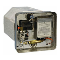
MAKING WATER CONNECTIONS
A. Water connections are made at the rear of the water heater. Refer to Figure 4. Connect the hot and cold water lines to
the 1/2” female pipe tting provided on rear of tank. These ttings are marked “HOT” and
“COLD”. NOTE: Inside each tting is a plastic ll tube. Its purpose is to enhance water
circulation. DO NOT REMOVE PLASTIC FILL TUBE.
IMPORTANT: Use a pipe thread compound suitable for potable water or pipe thread
tape on all connections to assure they will not leak.
B. Fill tank with water. Open both hot and cold water faucets to expel air from tank. When
tank is lled and water ows from faucets, close both faucets and check all connections
for leaks.
CAUTION: If you use air pressure to check for leaks, the pressure must not exceed 30
PSI.
NOTE: After leak testing, drain water from tank.
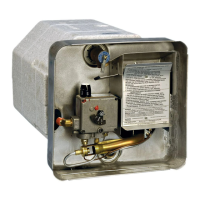
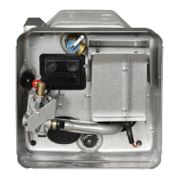
MAKING GAS
CONNECTIONS
A. Connect a 3/8” gas supply line to the 3/8 are tting at gas
valve located in the control housing. When making the gas
connection, hold the gas tting on the valve with a wrench
when tightening the are nut. Failure to hold tting secure
could result in a gas leak due to tting being damaged.
NOTE: It will be necessary to remove the grommet from
the control housing, make the gas connection at the valve,
then reinstall grommet.
B. Turn on gas and check all ttings and connections for leaks,
using a soap and water solution. Correct even the slightest
leak immediately.
HOT
COLD
GAS PRESSURE REQUIREMENTS
Supply Presure: Minimum 11” WC, Maximum 14” WC
WC = Water Column
Figure 4
GAS VALVE
GROMMET
(GAS INLET)
LE TUBE À GAZ
CONTROL HOUSING
ILLUSTRATED SHOWING
INSIDE OF HOUSING
LA BOÎTE DE COMMANDE
ILLUSTRÉE, MONTRANT
L'INTÉRIEUR DE LA BOÎTE
LA BAGUE
(L'ADMISSION
DE GAZ)
CAULK AND SEAL GROMMET (INCLUDING SLIT
AND TUBING) ALL AROUND AIR TIGHT
CALFATER ET ÉTANCHÉIER LA BAGUE (Y
COMPRIS LA FENTE ET LA COLONNE DE
PRODUCTION)
Figure 5
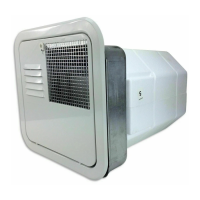
MAKING ELECTRICAL CONNECTIONS
A. Refer to Figure 2 (on page 8), for location of A.C. and D.C. junction box on specic models. All A.C. connections must
be inside junction box.
B. The electrical connections must be made in accordance with local codes and regulations. In the absence of local codes
and regulations, refer back to the installation and operation manual.
C. Be sure the switch for the electric element is “OFF” and that the water heater is lled with water before powering
element. Failure to do so will result in BURN-OUT of the electric element.
NOTE: Check rating plate and wiring diagram (Figure 6, 7, 8, 9, 10, 11) before proceeding. Install a fused safety
switch or circuit breaker of adequate capacity between heater and electrical power source. Attach the black and
white wires from the fused switch or breaker to corresponding colored wires in heater junction box. A wire from a
well grounded source must be attached to the green nut in the junction box.
DC/AC VOLTAGE REQUIREMENTS
Models with pilot reignitor and all DSI Models
All Models with electric elements 120 VAC Gas Control
Minimum 10.5 Volts D.C. Total connected Watts 1440 - 12 amps
Maximum 13.5 Volts D.C. 120 Volts A.C.
10
 Loading...