subzero.com | 7
Preparation
Uncrate the unit, and inspect for damage. Remove the
wood base, and discard the shipping bolts and brackets.
Remove and recycle packing materials. Do not discard the
kickplate, anti-tip bracket, and hardware.
Completely retract the front leveling legs to allow the unit
to be moved into position. The front and rear leveling legs
can be adjusted from the front once the unit is in position.
Remove the drain pan from the base of the unit to avoid
damage and to allow for proper placement of the appli-
ance dolly.
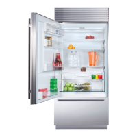
The grille assembly should be removed prior to moving the
unit. To remove, rotate the bottom of the grille upward.
Disconnect the network cable, then remove the center
mounting screw. Loosen the three grille bolts from the
grille, then pull the grille forward. Refer to the illustrations
below.
Lift grille
Grille removal
BOLT
CONNECTOR
SCREW
Plumbing Requirements
Installation must comply with all applicable plumbing codes.
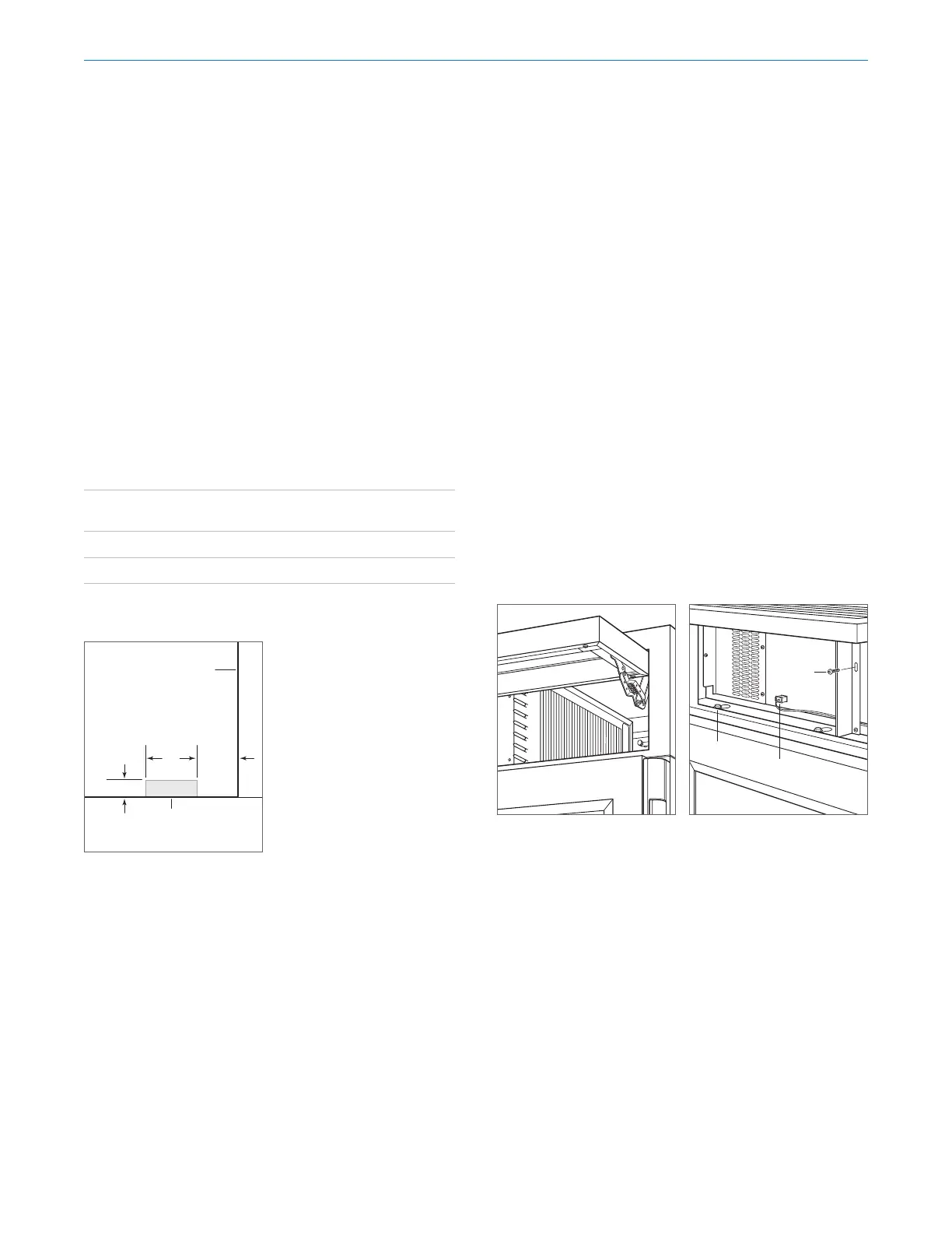
Locate the water supply line within the shaded area shown
in the illustration below. Connect the water supply line to
the house supply with an easily accessible shut-o valve.
Do not use self-piercing valves. The water supply line must
not interfere with the installation of the anti-tip bracket.
A reverse osmosis system can be used provided there is
constant water pressure of 35–120 psi
(2.4–8.3 bar) supplied
to the unit at all times. In this application, the water filtra-
tion system must be bypassed by removing the filter.
A copper line is not recommended for this application.
PLUMBING REQUIREMENTS
Water Supply ⁄" OD copper, braided
stainless steel, or PEX tubing
Pressure 35–120 psi (2.4–8.3 bar)
Excess Line for Connection 36" (914)
3" (76)
6"
(152)
5
3
/16"
(132)
RIGHT SIDE
OF OPENING
AREA EXTENDS
1
/2" (13)
FORWARD ON FLOOR
Water supply location
Site Preparation