Section 6
MAINTENANCE
27
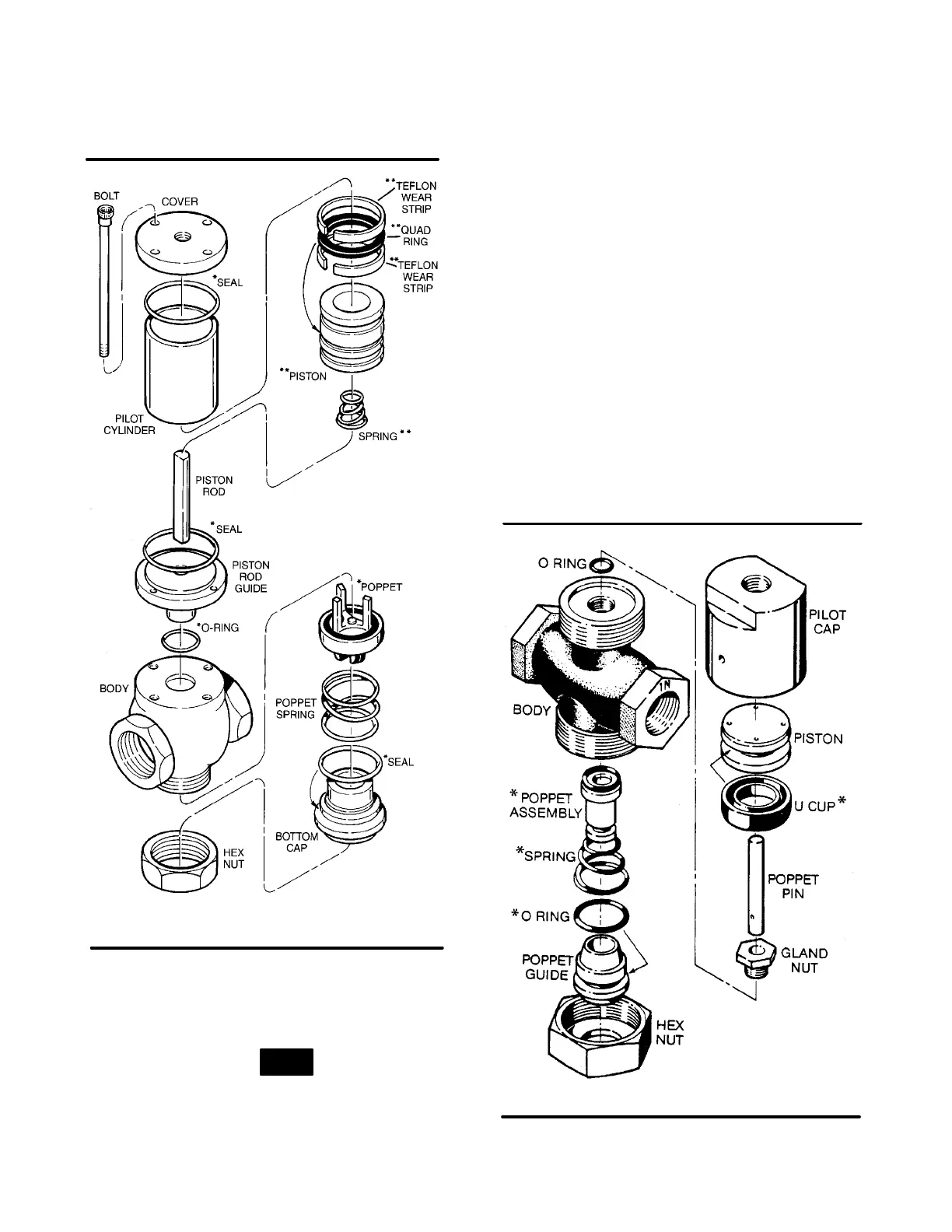
Figure 6-9 Fluid Stop Valve (P/N 250038-489)
* Repair Kit P/N 250038-494 (o-rings & poppet)
** Repair Kit P/N 250038-490 (piston & parts)
Super “O” ring seal or equivalent quality silicone
grease.
18. Install the piston into the pilot cylinder.
NOTE
Cylinder is chamfered on one end. Install from this
side.
19. Install the two (2) seals; one into the cover and the
other onto the piston rod guide.
20. Place cylinder over pilot guide.
21. Replace the cover and the four (4) nuts onto the
cover. Tighten nuts alternately at opposite sides
of the cover in a crisscross pattern. Check to see
that cylinder is seated on seals on both ends.
RUNNING BLOWDOWN VALVE MAINTENANCE
Refer to Figure 6-10. When it is necessary to repair
the running blowdown valve (P/N 045116), use re-
pair kit no. 047524, and follow the instructions pro-
vided below.
1. Remove the hex nut from the bottom of the valve.
The poppet guide which is secured by the hex nut
is under slight spring tension.
2. Remove the poppet guide, poppet assembly and
spring from the valve body.
3. Remove and discard the old o-ring on the poppet
guide and replace it with the new o-ring provided
in the kit. Be sure to lubricate the o-ring with a sili-
Figure 6-10 Running Blowdown Valve
* Repair Kit P/N 047524
(P/N 045116)

 Loading...

