Section 6
MAINTENANCE
28
cone base lubricant such as Parker Super “O”
lube or an equivalent quality grease.
4. Place the new spring and poppet assembly in the
valve body as shown. Then place the poppet
guide (with the o-ring in position) over the poppet
assembly.
5. Push the hex nut down over the poppet guide and
compress the spring whileturning the hex nut until
tight. Tighten securely with a wrench.
6. Remove the pilot cap from the top of the valve
body and pull the piston out of the cap.
7. Remove the U-cup from the piston and replace it
with the new one provided in the kit. The U-cup
should be lubricated with a silicone base lubricant
also.
8. Remove the gland nut from the valve body and pull
the poppet pin out to allow access to the small o-
ring in the top of the body.
9. Remove the small o-ring and replace it with the
new one provided in the kit. The o-ring must be lu-
bricated with a silicone base lubricant.
10. Replace the poppet pin and gland nut.
11. Place the piston with the new U-cup in position
back in the pilot cap with the recessed side show-
ing at the valve body end of the cap.
12. Replace the pilot cap and tighten securely with a
wrench. As this time the running blowdown valve
is ready to be installed for operation.
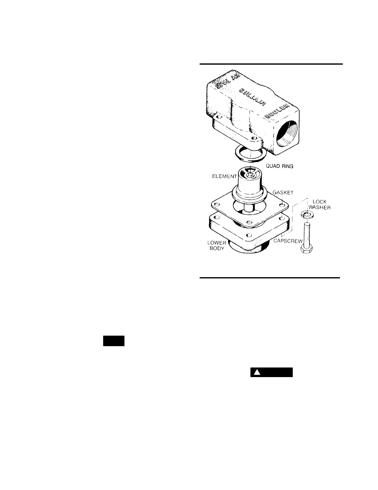
THERMAL VALVE MAINTENANCE
Refer to Figure 6-11. For thermal valve (P/N
250001-456) maintenance, order the following Sul-
lair parts: one (1) quad ring (P/N 046425), one (1)
gasket (P/N 049812) and if necessary, thermal ele-
ment P/N 250001-349. Follow the procedure ex-
plained below for installation.
DISASSEMBLY
1. Remove the appropriate piping from the thermal
valve before starting disassembly.
2. Remove the four (4) capscrews holding the hous-
ing together and separate the upper housing from
the lower housing.
3. Pull firmly on the thermal element and remove.
NOTE
There will be a slight resistance from the seal ring
centered in the lower housing.
4. Remove the seal ring from the lower housing and
discard.
REASSEMBLY
1. Grease and replace the gasket in the center of the
lower housing.
2. Reinsert the thermal element by pushing down
until the brass ring is flush with the surface of the
lower housing.
3. Position a new quad ring over the thermal ele-
ment.
Figure 6-11 Thermal Valve (P/N 250001-456)
* Element Replacement Kit P/N 250001-349
** Quad Ring Seal Replacement Kit P/N 046425
*** Gasket Replacement Kit P/N 049812
*
**
*
*
*
4. Place the upper housing on the lower housing and
retighten the capscrews.
5. Replace all piping connected to the thermal valve.
MINIMUM PRESSURE/CHECK VALVE MAINTE-
NANCE
Refer to Figure 6-12.Minimum pressure/check valve
(P/N250022-735) maintenanceis quiteminimal.The
only part which normally requires replacement is the
seal ring on thepiston. Toreplace this ring, orderseal
repair kit no. 250022-736 and follow the procedure
explained below.
WARNING
!
Before performing maintenance on the valve, be
sure that all pressure hasbeen relievedin thecom-
pressor sump, and all downstream pressure has
been vented to the atmosphere. Also be sure that
the components of the compressor are cool to the
touch.
1. Unscrew the minimum pressure/check valve (P/N
250022-735) from the receiver cover.
2. Remove the hexagonal retaining cover from the
main body.

 Loading...

