EasyManua.ls Logo

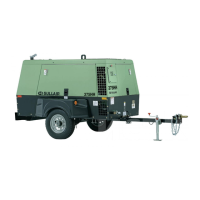
Sullair 300HH User Manual

Sullair 300HH
164 pages
To Next Page IconTo Next Page
Page #1 background imageLoading...
Page #1 background image
OPERATOR’S MANUAL AND PARTS LIST
Po r t a b l e ai r Co m P r e s s o r
300HH, 375, 375H, 375HH, 425
a n d 425H
John Deere Standard and Aftercooled and Filtered
PART NUMBER:
02250169-727 R02
©
SULLAIR CORPORATION
The information in this document
is correct at the time of printing for
portable compressor serial number
200803170000
and all subsequent serial numbers.
KEEP FOR
FUTURE
REFERENCE

Table of Contents

Other manuals for Sullair 300HH

Questions and Answers:

Sullair 300HH Specifications

General IconGeneral
Model300HH
Flow Rate300 cfm
Weight6, 100 lbs (2, 767 kg)
TypeRotary Screw Air Compressor
Drive TypeDirect

Summary

SAFETY

General Safety and Towing Procedures

General safety precautions, towing instructions, and preparation steps.

Parking, Pressure Release, and Fire Safety

Guidelines for parking, releasing pressure, and preventing fire/explosion hazards.

Operational Hazard Awareness

Safety regarding moving parts, hot surfaces, sharp edges, and toxic substances.

Electrical, Lifting, and Entrapment Safety

Precautions for electrical shock, lifting, and preventing entrapment.

Jump Starting and Lockout/Tagout

Procedures for jump starting and implementing lockout/tagout for maintenance.

California Proposition 65 Warning

Warning regarding California Proposition 65 concerning engine exhaust and battery components.

AIR CARE SEMINAR TRAINING

DESCRIPTION

2.1 Introduction and Components Overview

Overview of Sullair compressors and identification of main components.

2.3-2.6 System Functional Descriptions

Functional descriptions of compressor unit, cooling, discharge, and capacity control systems.

2.7-2.8 System and Panel Descriptions

Descriptions of air inlet system and instrument panel group functions.

Diagnostic Gauge and Engine Information Access

How to use the diagnostic gauge for engine info, configuration, and codes.

2.9 Wiring Diagram

Schematic diagram illustrating the compressor's electrical wiring.

2.10-2.13 System Descriptions and Codes

Descriptions of electrical, shutdown, aftercooled, and diagnostic codes systems.

SPECIFICATIONS

3.1 Model Specifications

Technical specifications for 300HH, 375, and 375H John Deere models.

3.2 Model Specifications

Technical specifications for 375HH, 425, and 425H John Deere models.

3.3-3.5 Lubrication and Application Guides

Guides for compressor and engine lubrication, and fluid application.

GENERAL

4.2 Purpose of Controls

Explanation of the function and location of various compressor controls and indicators.

4.3-4.4 Startup, Shutdown, and Restart Procedures

Step-by-step instructions for initial startup, shutdown, and subsequent restarts.

MAINTENANCE

5.1-5.7 Maintenance Schedules and Procedures

Daily, interval-based, and initial hour maintenance tasks for the compressor.

5.8 Part Replacement and Adjustment

Procedures for replacing parts and making adjustments to compressor components.

5.9 Trouble Shooting

Troubleshooting common symptoms, causes, and remedies for compressor issues.

NOISE CONTROL

6.1 Noise Emissions Warranty

Warranty information related to the noise emissions of the air compressor.

6.3 Noise Emissions Maintenance

Maintenance logs and procedures for noise emission control systems.

ILLUSTRATIONS AND PARTS LIST

7.1 Procedure for Ordering Parts

How to order replacement parts for the compressor, including contact information.

7.2 Recommended Spare Parts List

A list of recommended spare parts for the compressor.

7.3 Engine, Compressor and Parts

Illustrated parts breakdown for the engine and compressor assembly.

7.4 Radiator & Compressor Fluid Cooling System

Illustrated parts list for the radiator and fluid cooling system.

7.5 Air Inlet System & Exhaust System

Illustrated parts list for the air inlet and exhaust systems.

7.6 Control Parts & Discharge Parts

Illustrated parts list for control and discharge components on 375 and 425 models.

7.7 Control Parts & Discharge Parts

Illustrated parts list for control/discharge components on 300HH, 375H, 375HH, 425H models.

7.13 Electrical Parts

Illustrated parts list for the compressor's electrical system components.

7.14 Instrument Panel & Parts

Illustrated parts list for the instrument panel and its components.

7.16 Frame, Axle & Parts and Axle Assembly

Illustrated parts list for the frame, axle, and related assembly components.

7.18 Canopy, Acoustical Panels & Parts

Illustrated parts list for canopy and acoustical panels.

7.19 Decal Locations

Diagrams showing the location of various decals on the compressor.

7.20 Panel Color Part Number Reference

Reference table for part numbers based on panel color.

Related product manuals