3: Specifications 600H, 750, 750H, 750HH, 825, 900, 900H, 1050 T3 CAT User Manual
02250197-981 R01
42 Subject to EAR, ECCN EAR99 and related export control restrictions.
3.4 Lubrication guide, compressor
3.5 Application guide
Refer to Figure 3-1. Sullair Air Compressors are supplied
with Sullair AWF
®
which is heavy duty multi-viscosity, all
weather fluid. Sullair AWF also allows an extended
change interval. The fluids in Section 3.4: Lubrication
guide, compressor can be used. Any of these oils are
suitable under conditions where severe oil oxidations can
o
ccur.
Water must be drained from the receiver tank peri-
odically.
In high ambient temperature and high humidity condi-
tions, condensed moisture may emulsify with the oil fo
rm-
ing a “milky” color. ATF or SAE 10W is especially prone
to this cond
ition. The fluid should be changed if this con-
dition develops.
When ambient conditions exceed those noted or if condi-
tions warrant use of other extended life lubr
icants, con-
tact Sullair for recommendations.
Sullair encourages the user to participate in a fluid analy-
sis program. This could result in a fluid change interval
diff
ering from that stated in the manual. Sullair offers a
fluid analysis program for Sullair AWF. Contact your local
Sullair representative for details.
3.6 Lubrication guide, engine
For engine oil specifications, refer to the Engine Opera-
tor’s Manual.
Fluid type Change period, hours Ambient temperature range °F (°C)
Sullair AWF
®1
1500 −20 to 120 (−29 to 49)
1
Sullair part numbers for multi-viscosity lubricants are 250030-757 (5 gallons/18.9 liters), 250030-758 (55 gallons, 208 liter drum)
CAUTION
DO NOT mix types of fluids. Combinations of dif-
ferent fluids may lead to operational problems
such as foaming, filter plugging, orifice or line
plugging.
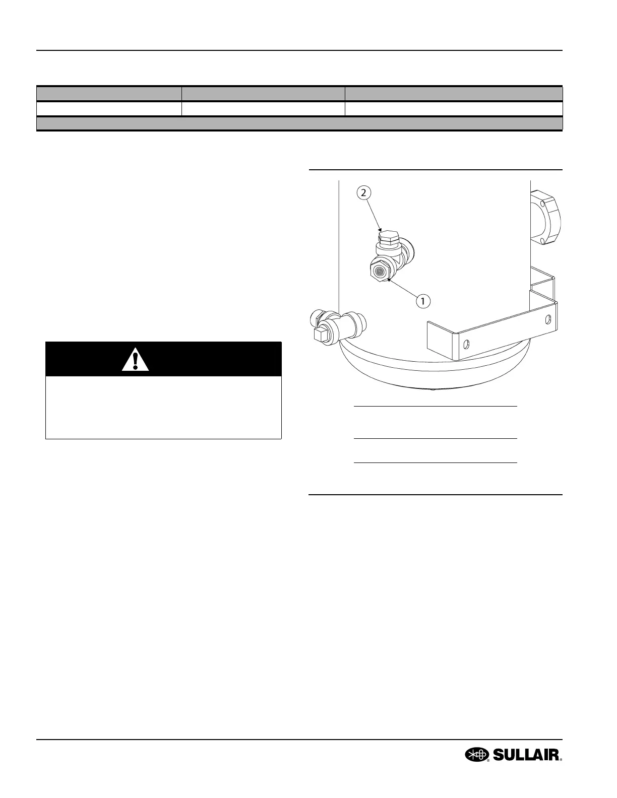
Figure 3-1: Fluid fill location
1. Sight glass
1
2. Fluid fill port
1
If fluid is seen in the sight glass when the
machine is not running, no fluid is needed.
 Loading...