6 Electrical Connection User Manual
22
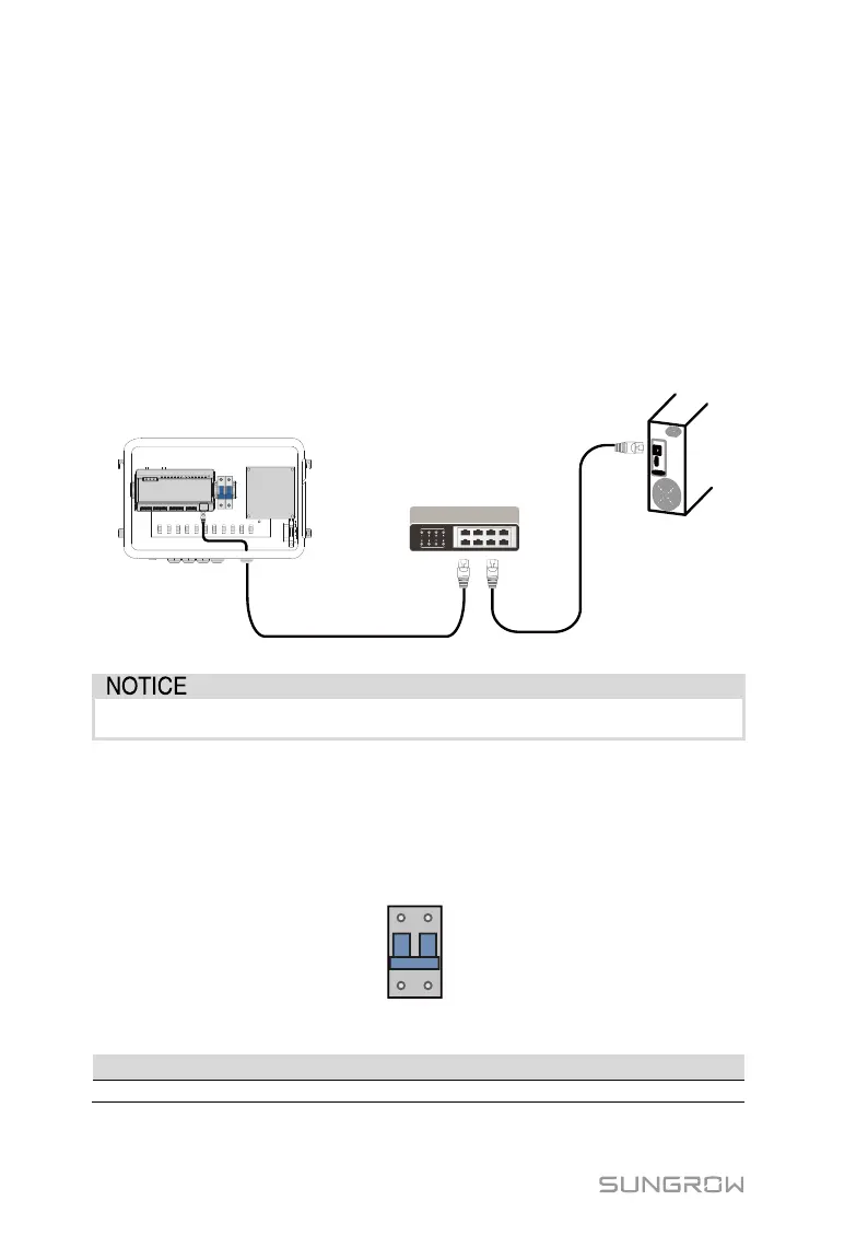
6.6 Ethernet Port
The COM100 can be connected to the background of the PV system via the
Ethernet port, and the communication protocol is standard Modbus TCP or
IEC104.
Step 1 Prepare a suitable length of Ethernet cable.
Step 2 Insert one end of the cable into the port of the Ethernet switch and the
other end to the "ETH" port of the Logger1000 inside the COM100.
Step 3 Set IP address of the ETH port to be within the same network segment
as that of the background monitoring system.
Fig. 6-2 Connection to PV background system
Default IP of the "ETH": IP12.12.12.12.
6.7 External AC Power Supply Cable
External AC power supply ports are provided on the bottom of external power
supply circuit breaker inside the COM100, as shown in the figure below.
Power cable specification:
Outdoor ultraviolet protection cable
Step 1 Loosen the "AC (100~277V)" waterproof terminal, and insert the external