20
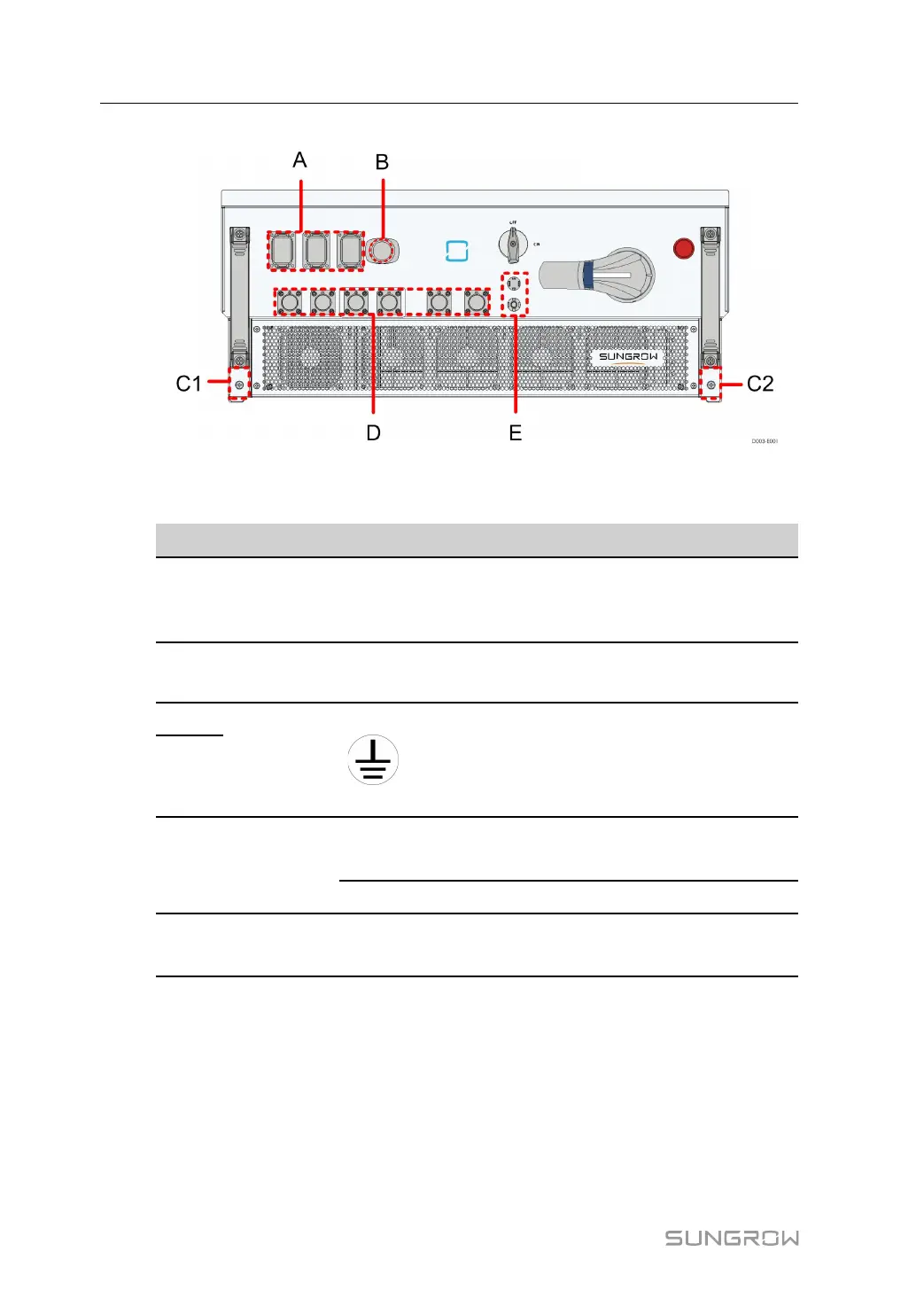
FFiigguurree 55--11 Wiring terminals
*Image shown here is for reference only. The actual product you receive may differ.
IItteemm TTeerrmmiinnaall MMaarrkk NNoottee
A
Communica-
tion terminal
COMM1/
COMM2/
COMM3
RS485 communication, and digital input/
output DI/DO.
B
Ethernet
terminal
Ethernet
To connect to BMS or router or data
collector.
C1
PE terminal
To ground the system protection. Config-
ure multiple PE terminals to facilitate the in-
terconnection of the grounding points of
multiple converters.
C2
D
DC terminal
1/2/3
DC1+/DC1-
DC2+/DC2-
To connect to the storage battery.
DC3+/DC3- To connect to the inverter.
E
Power sup-
ply terminal
1500V
To supply power to the BMS.
5.3 Electrical Connection Overview
Electrical connection in the energy storage system includes additional grounding con-
nection, DC connection, and communication connection.
5 Electrical Connection User Manual