11-6
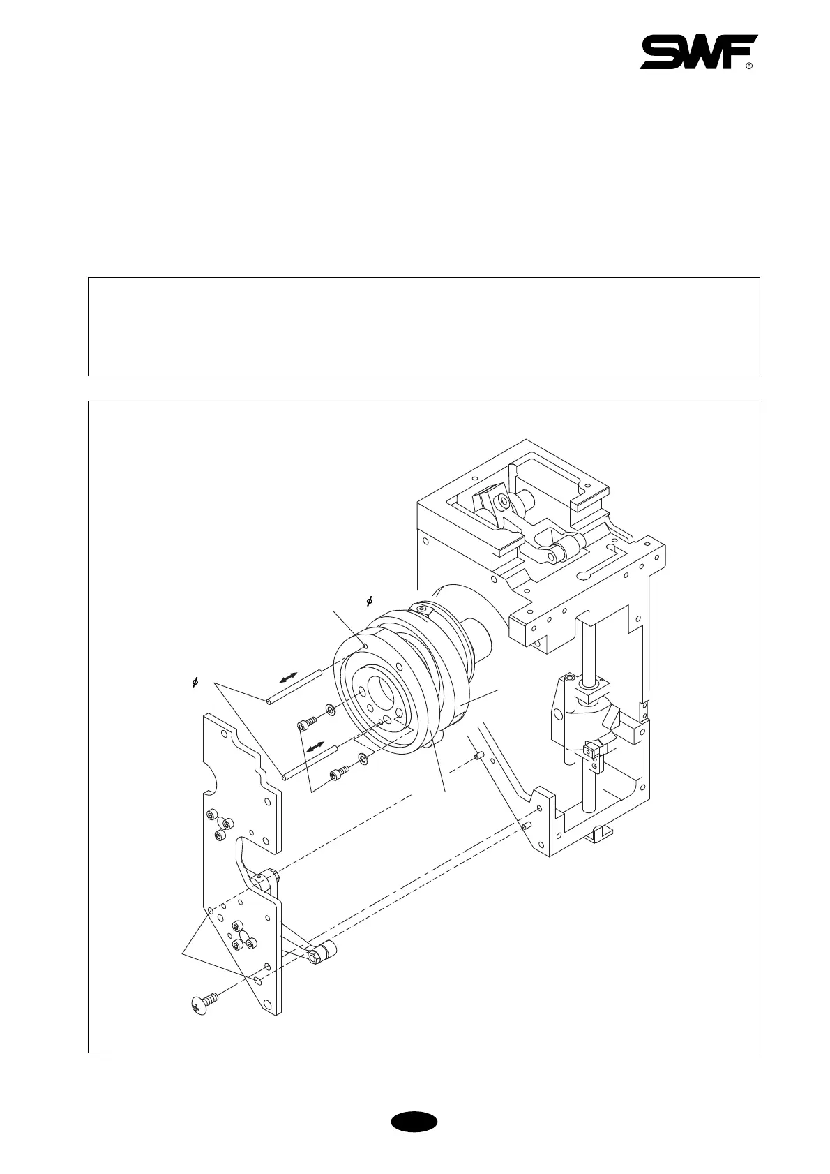
11-6) ADJUSTING LOW-NOISE PRESSER FOOT
1) Assembly of Presser Foot Cam
① Set the main shaft at 178° and install two reference pins (ф3) into the assembly hole of the presser foot
driver cam (ф3) as shown in [Fig.11-12]. Insert the pins then into the assembly hole of the take-up lever
driver cam.
② Adjust the presser foot driver cam to where the reference pins freely move left and right. Fix the three
screws (M4×L35).
[CAUTION]
1. The assembly pin should smoothly move right and left with the three screws fastened.
2. The assembly unit and the assembly pin are not for commercial sale.
3. Contact your SWF dealer if you must adjust the location of the cam.
[Fig.11-12]
Reference pins ( 3)
Hole (
3)
Assembly hole
Screw (3)
Presser foot
drive cam
Take-up lever
drive cam
 Loading...