Questions? Call or Text +1-801-658-0015 • 3
e Micro Welder Experts
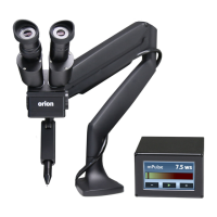
Figure 3.1. Attach Clamp
Mechanism (D) to angled
bracket (C).
Figure 3.2. Cover the Clamp
Mechanism (D) with the
plastic cable guide cover (E).
Arm Assembly using three (3) of the included
at head hex screws (G) using a 4mm (5/16”)
Allen wrench (L).
• Attach the Clamp Mechanism (D) to the Angled
Bracket using two (2) of the included at head
hex screws. See Figure 2.3. For thicker tables,
attach the clamp mechanism (D) to the two
lower holes in the Angled Bracket (C).
• Adjust the knob on the Clamp Mechanism (D)
until the gap is sucient for the thickness of
your tabletop.
• Lock the arm into place by turning the knob
on the Clamp Mechanism (D) until the clamp is
pressing rmly against the bottom of the table.
• Lift the Microscope Arm Assembly (A) up, slide
the arm onto the table as shown in Figure 3.1.
• A plastic cable guide cover (E) can be clipped
on over the angled bracket if desired. See
Figure 3.2.
Mounting Option 2 - Bolt through Table
Mounting Option 2 is best for tables without accessible
edges. Hardware required from Box 2:
(1) Flat Mounting Plate (H)
(3) Flat Head Hex Screws (G)
(1) Long Carriage Bolt (F)
(1) Flat Pressure Plate (I)
(1) Adjustment Knob (J)
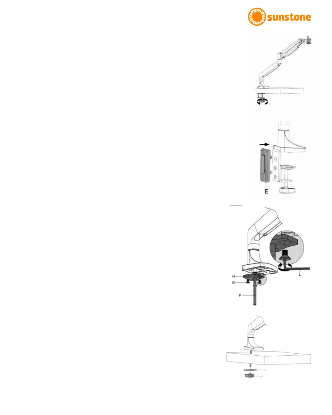
• As shown in Figure 3.3, using a 4mm (5/32”)
Allen wrench, unscrew the at head hex screws
(G) holding the Flat Mounting Plate (H) to the
arm.
• Run the included 8mm (5/16”) Long Carriage
Bolt (F) through the included Flat Mounting
Plate (H).
• Attach Flat Mounting Plate (H) to the bottom of
the arm using (3) at head hex screws (G).
• Drill a 3/8” (9.5mm) hole through the tabletop.
Figure 3.3. Remove the
plate from the arm, run
the carriage bolt (F)
through the mounting
plate (H), then re-attach
the mounting plate to
the arm.
Figure 3.4. Lower the
arm so the bolt goes
through the hole in the
table.