4 • Questions? Call or Text +1-801-658-0015
Orion
™
mPulse User Manual
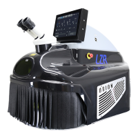
• Lower the arm so the Long Carriage Bolt (F)
goes through the hole in the tabletop. See
Figure 3.4.
• Slide the Flat Pressure Plate (I) onto the bolt.
Turn the Adjustment knob (J) clockwise to
tighten the plate to the underside of the table.
See Figure 4.1.
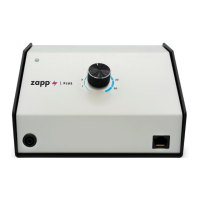
Mounting Option 3 - Screw to Table (vertical
surface)
Required hardware from Box 2:
(1) Angled Mount Bracket
(3) Flat Head Screws
(2) Wood Screws (not included)
• Attach the Angled Bracket (A) to the bottom of
the Microscope Arm Assembly (B) using three
(3) of the included at head hex screws (G) as
shown in Figure 2.2.
• Lift and position the arm assembly onto the
table in the desired location.
• Run wood screws through the Mounting
Bracket (A) and into a vertical surface of the
table, as shown in Figure 4.2.
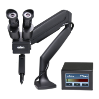
ARM TENSION ADJUSTMENT
The spring tension is factory pre-set, but should chang-
es be desired, the tension can be adjusted by turning a
hex screw located on the arm joint, as shown in Figure
4.4. Use the included 6mm Allen wrench to make ad-
justments.
• Turn the hex screw counterclockwise (in the
direction of the “+” symbol on the arm) if the
arm does not hold the microscope up.
• Turn the hex screw clockwise (in the direction
of the “-“ symbol) if the arm does not allow the
microscope to be lowered easily.
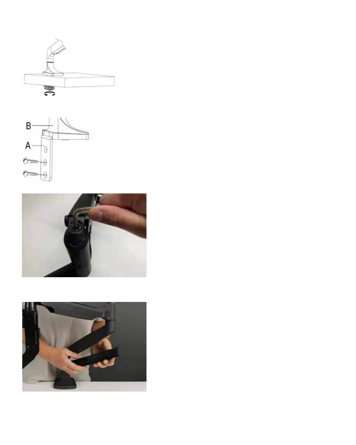
For cable management, tubes and cables can be routed
through a removable guide as shown in Figure 4.5.
Figure 4.4. Adjust the tension of the Microscope Arm
Assembly for more loose or more tight movement.
Figure 4.5. Tubing and other cables can be routed up and
through the removable cable guide portion of the arm.
Figure 4.1. Turn the Adjustment knob (J)
clockwise to tighten the plate to the table.
Figure 4.2. Use wood screws (not
included) to attach the Angled
Mount Bracket (A) to the table.