2 • Questions? Call or Text +1-801-658-0015
Zapp
™
User Manual
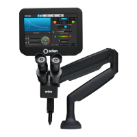
Figure 2.1. To install the electrode, rst remove the Stylus
Shaft (A) from the Stylus Hull (E) by pulling them apart.
Figure 2.2. Use the guide on the side of the Stylus Hull (E) for
proper Electrode (D) positioning.
Install the Tungsten Electrode Onto the
Welding Stylus
Refer to the Stylus Components Chart (Figure 2.4) to install
the tungsten electrode (D).
• Remove the Stylus Hull (E) by pulling it away from
the Stylus Shaft (A). See Figure 2.1.
• Loosen the Collet Cap (C) by twisting it counter-
clockwise.
The welder accommodates 0.5mm and 1.0mm electrodes.
The electrode stylus will be shipped with the 1.0mm elec-
trode collet installed.
• Insert a 1.0mm electrode (D) into the Collet (B).
Helpful Tip: There is a machined groove on the side of
the Stylus Hull (E) that helps measure the electrode
length. Place the end of the Stylus Hull (E) against
the Collet Cap (C), then make sure the Electrode (D)
extends as indicated. See Figure 2.2.
• There should be between 0.6 - 0.7 inch (1.5 – 2cm)
of the Electrode (D) protruding from the Stylus
Shaft (A). This will allow the Electrode enough room
to stick out from the Stylus Shaft once the Stylus
Hull (E) is placed back on the Stylus Shaft.
• Lock the Electrode (D) into place by hand tightening
the Collet Cap (C) in a clockwise direction.
• Replace the Stylus Hull (E) by pushing it in until
you feel it snap back into place. The Electrode (D)
should protrude from the Stylus Hull (E) by 1/8 –
1/4 inch (3.175 – 6.35mm) after the Stylus Hull is
snapped back into place. See Figure 2.3.
Figure 2.3. Electrodes should protrude past the stylus
hull 1/8 to 1/4 inch (3.175 to 6.35mm).
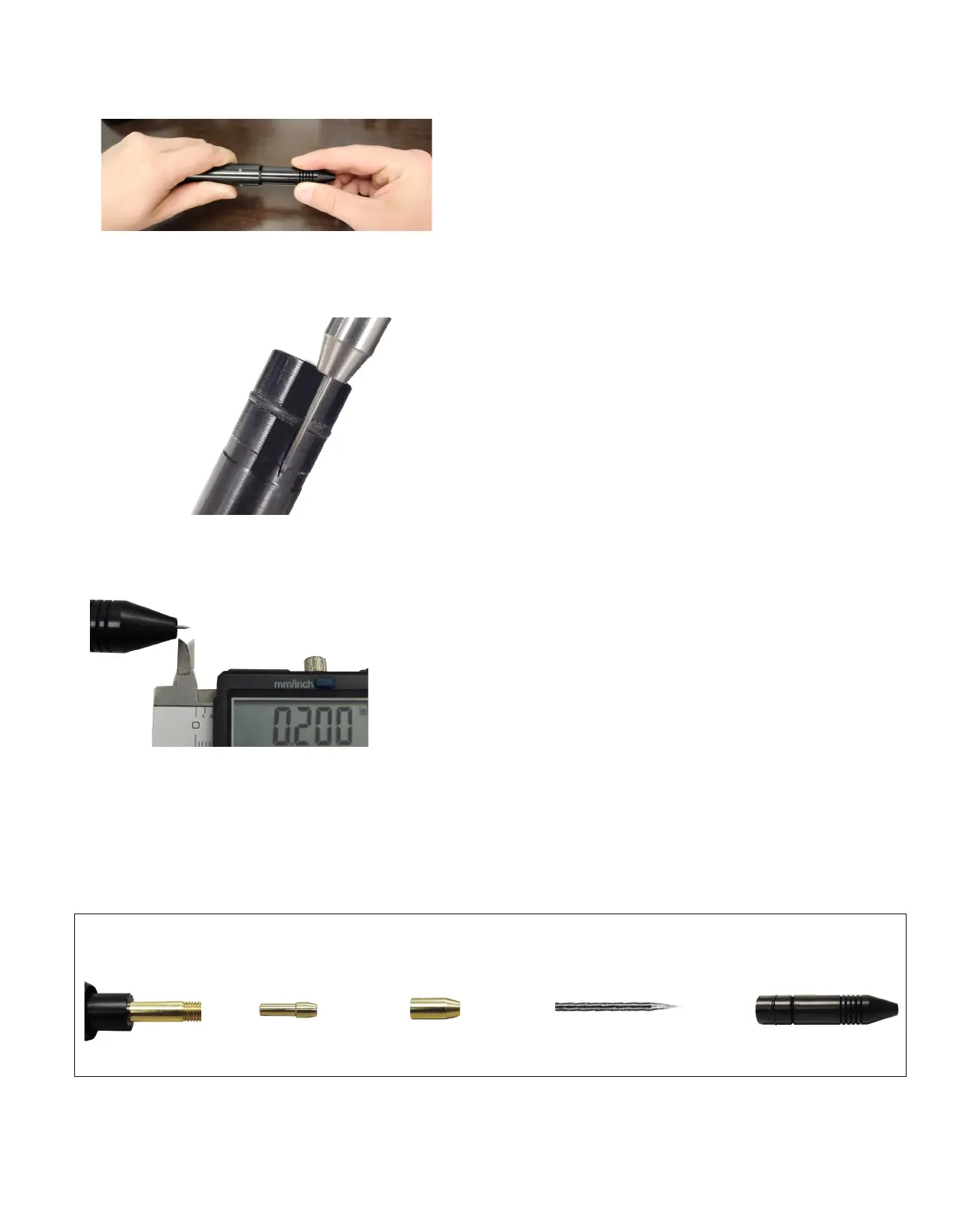
Stylus Shaft A Collet B Collet Cap C Electrode D Stylus Hull E
Stylus Components
Figure 2.4.