Page | 41
Gen Max Run Time: This indicates the longest time the generator can run in one day.
When the maximum running time is reached, the generator will be turned off. ‘24H’ means
the generator will run continuously.
Gen Down Time: This indicates the delay-time of the generator to shut down after it has
reached the running time
Grid Charge: It indicates that the grid will charge the battery.
Grid Signal: Indicates when the grid should no longer charge the battery.
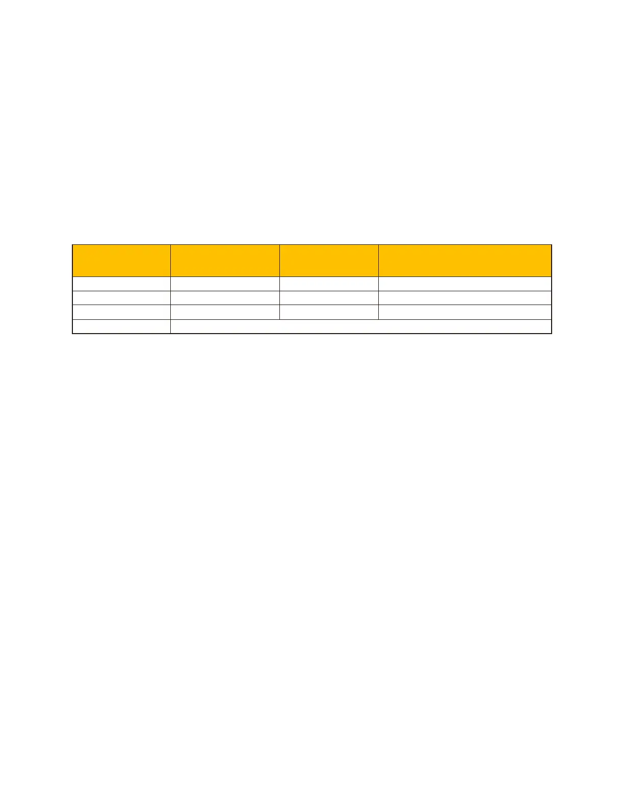
Recommended battery settings:
Battery Type
Absorption
Stage
Float Stage
Voltage (every 30 days 3hr)
AGM (or PCC) 14.2V (57.6V) 13.4V (53.6V) 14.2V (57.6V)
Gel 14.1V (56.4V) 13.5V (54.0V)
Wet 14.7V (59.0V) 13.7V (55.0V) 14.7V (59.0V)
Lithium Follow its BMS voltage parameters
Using a generator with a Sunsynk inverter:
A generator can either be connected to the Grid side or to the Gen connection. When
connected to the Grid Input, the inverter will consider the power coming from the generator
as ‘Grid Supply’. Users should make sure this power goes to the LOAD only and should
not be exported to other outlets as this will damage the generator.
An advantage from connecting the generator to the Grid Input is is that it can be paralleled
whereas the GEN/AUX input cannot be paralleled. That means the inverter will extract
what power it requires from ‘Grid Supply’ to charge its batteries.
If the generator is connected to the inverter and a generating signal exists, the inverter will
switch 100% of the load to the generator and then slowly increase the charging currents
to the batteries. Therefore, the generator must be able to supply both the charge current
and the total load current.
The generator can be controlled via a relay which has a set of dry-contacts to enable
remote control. The current on thee contacts is limited to approximately, 1Amp 12V.
Below is a simple reference circuit of an auto start system that can autostart generators
on a boat. (Sunsynk will be releasing a new OS E406 ( Auto-Start ) for better generator
control)
 Loading...