Do you have a question about the Suntex PC-3100 and is the answer not in the manual?
Describes how the controller can be installed via panel, wall, or pipe mounting.
Provides visual guidance and dimensions for panel mounting the controller.
Visual guide for wall and pipe mounting methods, including order numbers.
Details the correct setup procedure for the coaxial electrode cable.
Step-by-step instructions for assembling the PP-100A electrode housing.
Explains the junction box structure and wiring for two-wire distribution systems.
Shows the layout of the rear panel connections and labels.
Diagrams the function of each terminal connection on the controller.
Provides detailed explanations for each terminal's purpose and connection.
Guidance on installing the optional PH-300T transmitter for remote measurement.
Details the electrical connections between the controller and the PH-300T transmitter.
Illustrates common wiring configurations for two-wire and three-wire distribution.
A schematic showing the overall electrical connections for the controller and external devices.
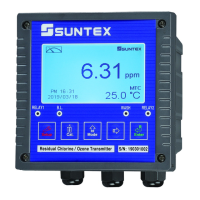
Visual representation of the controller's front panel interface and display.
Explains the function of each button on the controller's keypad.
Describes the meaning and function of each LED indicator on the front panel.
Details the various elements and information displayed on the controller's screen.
Outlines the process to start and monitor measurements after setup.
Guides users to access and navigate the parameter setup menu.
Instructions on how to enter and perform calibration procedures.
Procedures for restoring factory default settings or calibration data.
Instructions for setting the system time and date on the PC-3100RS model.
Explains how to access the parameter setup interface.
Details how to set, use, and reset the security code for settings.
Guides the configuration of measurement parameters like pH or ORP.
Instructions for setting temperature compensation and correction parameters.
Configuration of the high threshold (Hi) and deadband for relay control.
Configuration of the low threshold (Lo) and deadband for relay control.
Setting the automatic start and stop times for the electrode washing function.
Adjusting the relationship between pH/ORP range and output current.
Adjusting the relationship between temperature range and output current.
Setting the current date and time for the controller.
Configuring ID and transmission speed for RS-485 communication.
Adjusting the LCD backlight brightness and sensitivity settings.
Procedures for setting up and using a security code for calibration access.
Steps to access the calibration menu and its sub-options.
Detailed instructions for single-point and dual-point asymmetry calibration.
Guidance for dual-point and three-point calibration using TECH buffers.
Procedure for adjusting the zero-point electrical potential for ORP measurement.
Diagrams the physical connections and network setup for RS-485 communication.
Command set for reading data and status from the controller in measurement mode.
Command set for reading configuration parameters in set-up mode.
| Brand | Suntex |
|---|---|
| Model | PC-3100 |
| Category | Controller |
| Language | English |