28 29
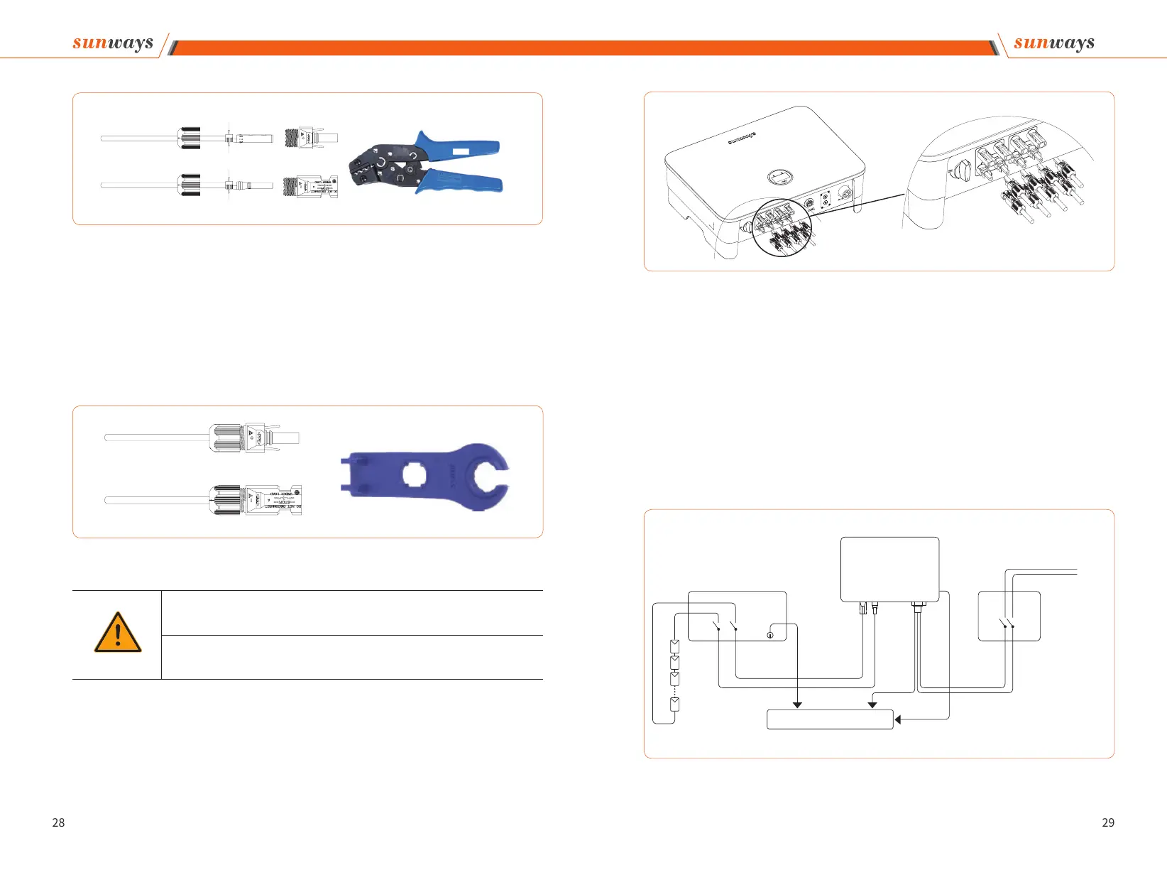
⑤ Insert the positive and negative cables into the corresponding positive and negative con-
nectors, pull back the DC cable to ensure that the terminal is tightly attached in the connec-
tor.
⑥ Use an open-end wrench to screw the nut to the end to ensure that the terminal is well
sealed, as shown in Figure 4-17:
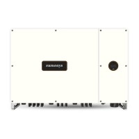
3. Insert the positive and negative connectors into the inverter DC input terminals respec-
tively, a click sound should be heard if the terminals are well connected, as shown in Fig-
ure 4-18:
Figure 4-16
Crimping Plier
Figure 4-17
Open-end Wrench
Warning
① Before assembling the DC connector, make sure that the cable polarity is correct.
② Use a multimeter to measure the voltage of the DC input string, verify the polarity of
the DC input cable, and ensure that each string voltage is within 1000V.
4 Installation
Figure 4-18
DC Switch
Inverter
PE
PE
L
N
To grounding electrode
-
-
+
+
Grid
AC Breaker
DC INPUT AC OUTPUT
Figure 4-19
4. Seal the unused PV terminals with the terminal caps.
5. System Layout of Units without Integrated DC Switch
Local standards or codes may require that PV systems are fitted with an external DC
switch on the DC side. The DC switch must be able to safely disconnect the open-circuit
voltage of the PV array plus a safety reserve of 20%. Install a DC switch to each PV string
to isolate the DC side of the inverter. We recommend the following electrical connection,
as shown in Figure 4-19:
4 Installation
COM2-1
COM2-2