30 31
4.5.2 Connection of AC output
Before connecting to the power grid, make sure that the power grid voltage and frequen-
cy meet the requirements of the inverter. See technical parameters for details.
This inverter includes an integrated residual current device (RCD).
If an external residual current device (RCD) is used, a device of type (A/AC etc.) should be
used, with a tripping current of 300mA or higher.
The recommended cable and AC switch for the Sunways STT 4-25kW series three phase
inverter are shown in the following table:
Figure 4-20
Model
STT-4K STT-5K STT-6K STT-8K STT-10K STT-12K STT-15K STT-17K STT-20K STT-25K
Coper
Cable
2.5-10
mm
2
2.5-10
mm
2
2.5-10
mm
2
4-10
mm
2
4-10
mm
2
4-10
mm
2
6-10
mm
2
8-10
mm
2
8-10
mm
2
8-10
mm
2
Breaker 20A 20A 20A 20A 32A 32A 32A 40A 40A 50A
Warning
An AC breaker must be connected on the AC side of the inverter.
Any loads cannot be connected to the inverter without the AC breaker.
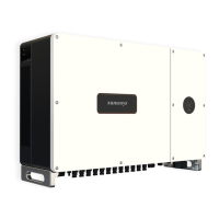
1. AC connector connection steps
① Take the AC connector out of the accessory bag and disassemble it, as shown in Figure
4-20:
4 Installation
Cable Gland Threaded Sleeve AC Terminal Head
Figure 4-21
Figure 4-22
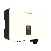
③ Insert the stripped end of the ve wires into the appropriate hole of the terminal head
by following the rules: yellow green wire to PE port, red or brown re wires to L ports (no
requests for the sequence of three re wires), and blue or black wire to the N port. Please
try to pull out the cable to make sure it is well connected. As shown in Figure 4-22:
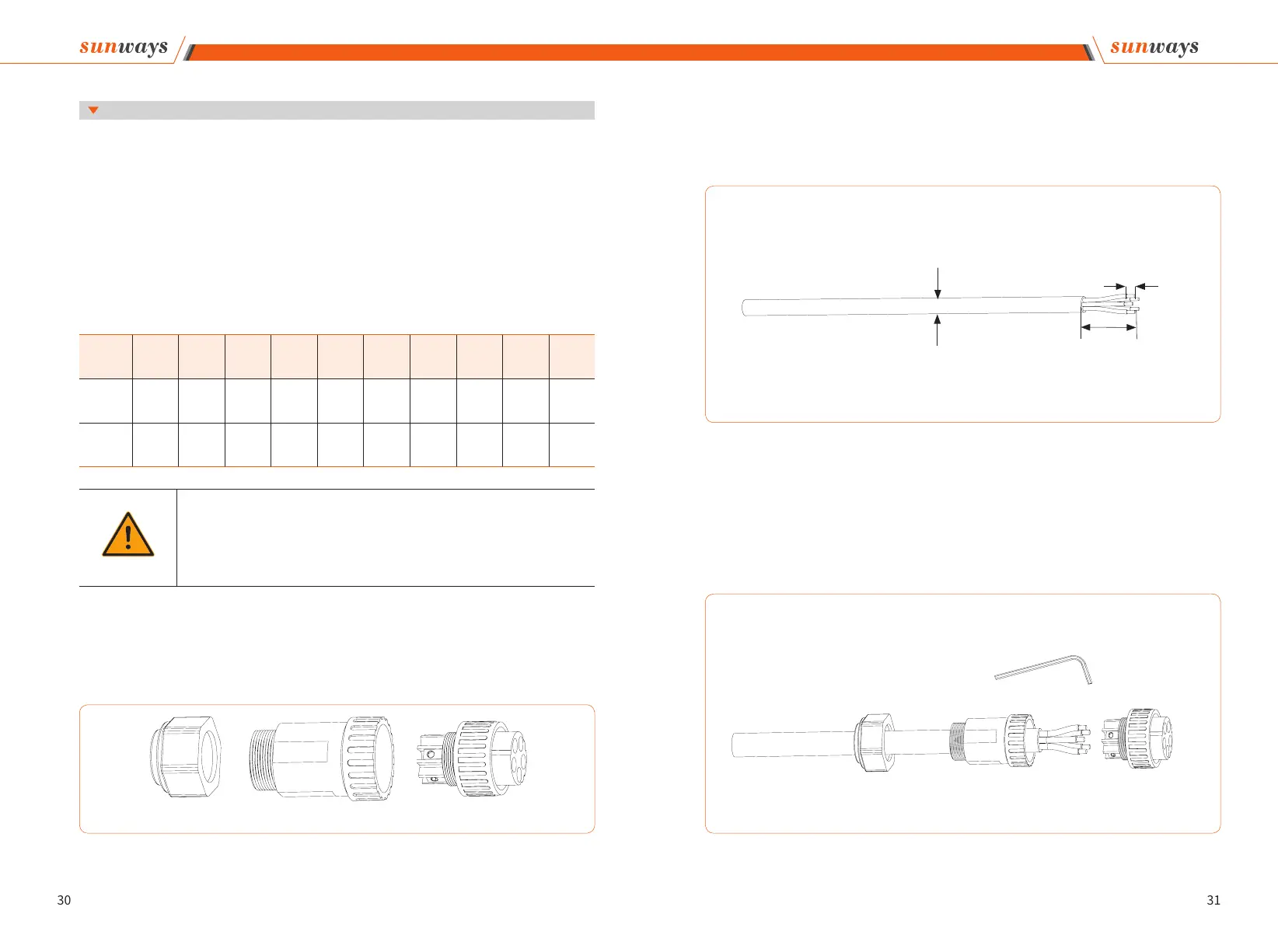
② According to the table above, select an appropriate cable, peel the insulation sleeve of
AC cable o for 50mm, and peel o the end of 3L /PE / N wires for 8mm, as shown in Fig-
ure 4-21:
4 Installation
Strip Length:8mm
50mm
Wire Diameter:13-18mm
Allen Key